EasyManua.ls Logo

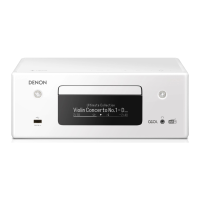
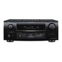
Denon RCD-N9

Denon RCD-N9
91 pages
To Next Page IconTo Next Page
To Previous Page IconTo Previous Page
Loading...
TAS5142 Block Diagram
www.ti.com
FUNCTIONAL BLOCK DIAGRAM
Temp.
Sense
M1
M2
RESET_AB
SD
OTW
AGND
OC_ADJ
VREG VREG
VDD
M3
Power
On
Reset
Under-
voltage
Protection
GND
PWM_D OUT_D
GND_D
PVDD_D
BST_D
Timing
Gate
Drive
PWM
Rcv.
Overload
Protection
I
sense
GVDD_D
RESET_CD
4
Protection
and
I/O Logic
PWM_C OUT_C
GND_C
PVDD_C
BST_C
Timing
Gate
Drive
Ctrl.
PWM
Rcv.
GVDD_C
PWM_B OUT_B
GND_B
PVDD_B
BST_B
Timing
Gate
Drive
Ctrl.
PWM
Rcv.
GVDD_B
PWM_A OUT_A
GND_A
PVDD_A
BST_A
Timing
Gate
Drive
Ctrl.
PWM
Rcv.
GVDD_A
Ctrl.
BTL/PBTL−Configuration
Pulldown Resistor
BTL/PBTL−Configuration
Pulldown Resistor
BTL/PBTL−Configuration
Pulldown Resistor
BTL/PBTL−Configuration
Pulldown Resistor
Internal Pullup
Resistors to VREG
B0034-02
TAS5142
SLES126BDECEMBER 2004 REVISED MAY 2005
7
72

Related product manuals