- 16 -
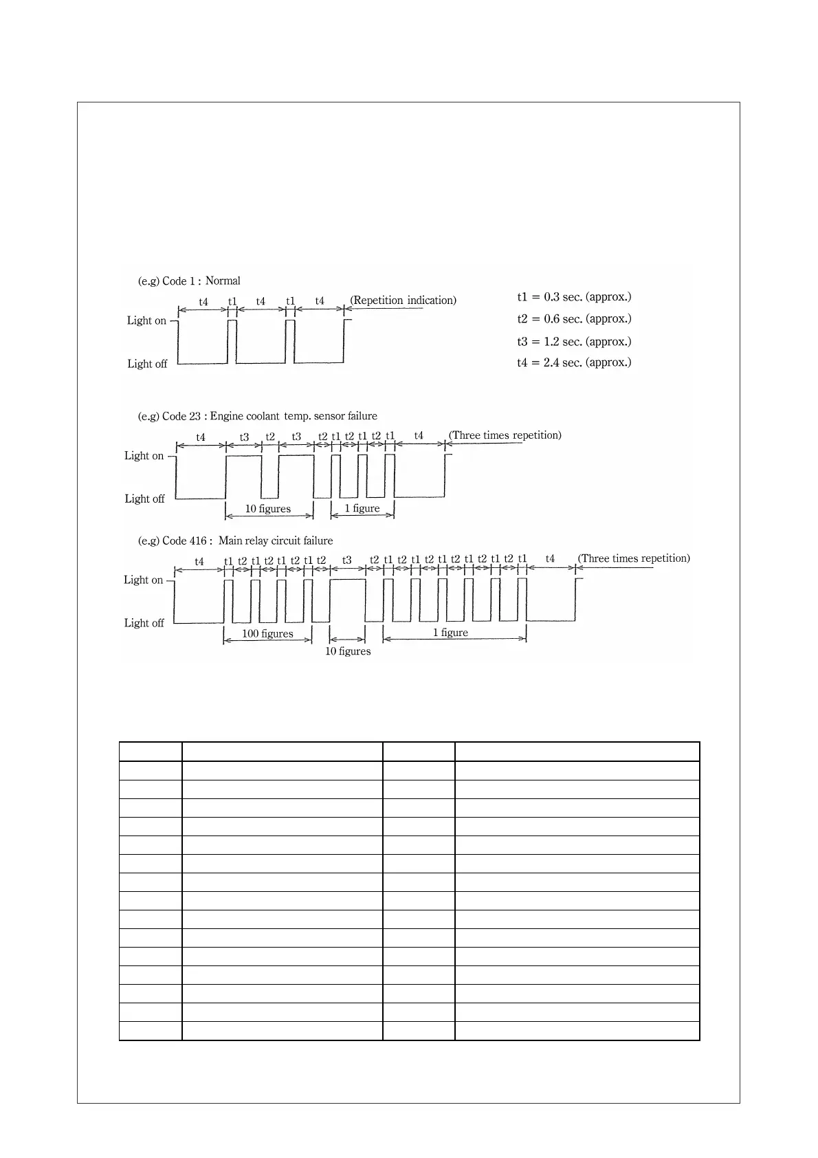
2. If abnormal operation, push the “DIAGNOSTIC BUTTON”. Continue pushing the
“DIAGNOSTIC BUTTON”, and the failure code will appear (Blinking display).
• If operation is normal, the code “1” will repeatedly blink.
• If operation is abnormal, the failure code will blink three times. If there is more than
1 failure, it will repeat the codes in ascending order. So it would indicate the first
failure three times, and then indicate the second failure three times, etc.
After it has indicated all failure codes, it will repeat from the first failure code.
• While the engine is in operation, if a failure occurs, the “DIAGNOSTIC LAMP” will
light, but cannot indicate the failure code.
FAILURE DIAGNOSIS DISPLAY CODE
CODE LOCATION OF FAULT CODE LOCATION OF FAULT
01 Normal Condition 118・151 Common Rail Pressures
14 Cam Sensor 158・159 Injector Drive Circuit
15 Crank Sensor 211 Fuel Temp. Sensor
16 Cam-Crank Pulse 225 Rail Pressure Limiter Open
19 Starter Cut Relay 227 Fuel Rail Pressure is Low (Fuel Leak)
22 Intake Air Temp. Sensor 245 Fuel Rail Pressure Sensor
23 Engine Coolant Temp. Sensor 247 Fuel Pressure Regulator Control Circuit
32 Boost Pressure Sensor 271~276 Injector Circuit
34 ECM Charge Circuit 294 Engine Oil Pressure Sensor
36 A/D Conversion 295 Boost Temp. Sensor
44・45 EGR 416 Main Relay Circuit
51~54 Engine Controller 542 Over Heat
55 5 Volt Circuit 543 Engine Over Run
66 Glow Relay
71 Barometric Pressure Sensor
Check all of the connections. If connections are sound, Contact the Service department
for repairs.