- 10 -
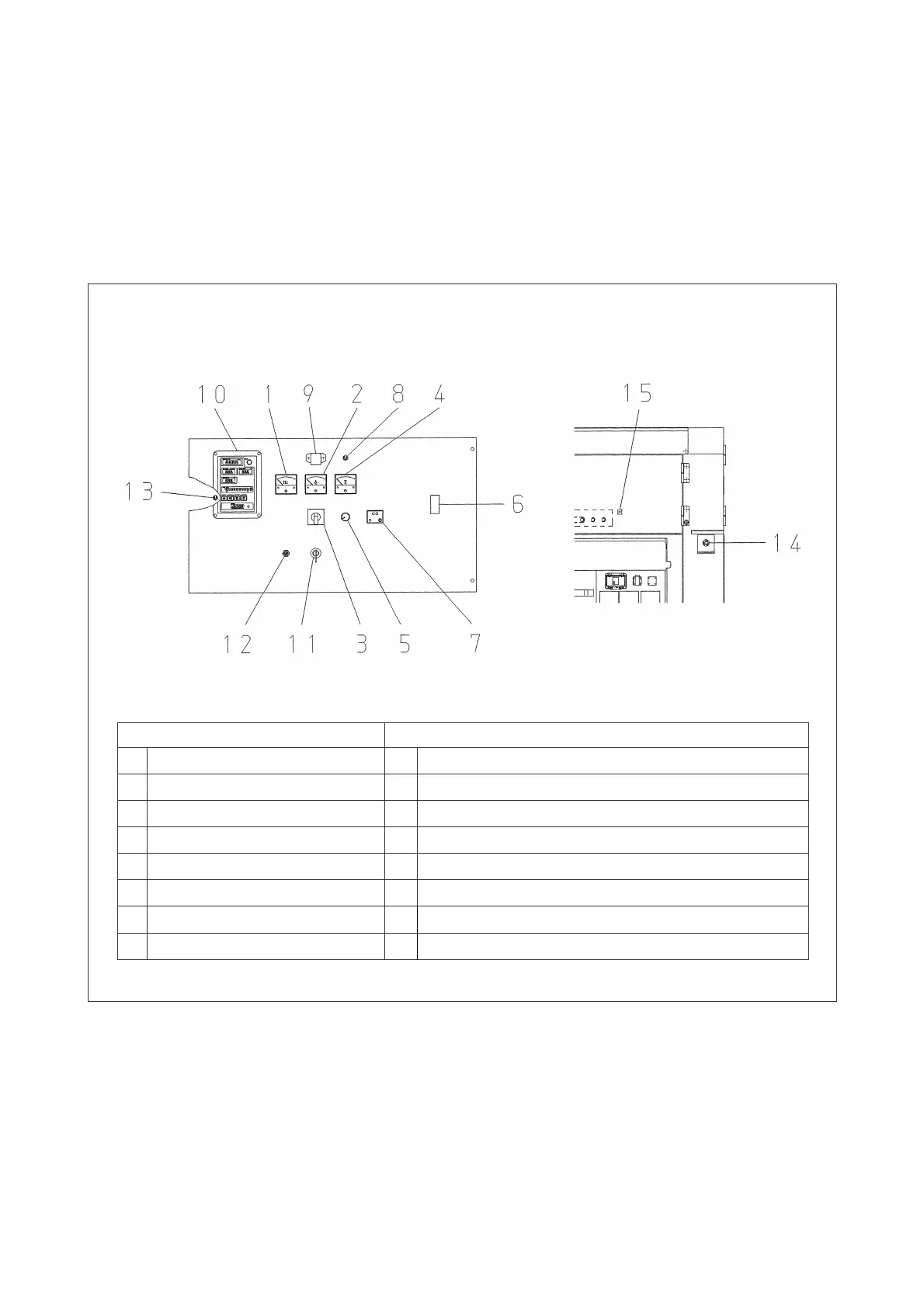
1-4 Control switches and meters
• The control switches and meters are located inside the door having a window on the rear of
the machine.
• The control panel is mounted on the bodywork with hinges and is fastened by screws.
Loosening the screws has access to repairing or replacing electrical parts in the control
box.
1-4-1 Engine start/stop controls
Fig. 3
Parts number
Parts number
1. Frequency meter 8. Panel light switch
2. Ac ammeter 9. Panel light
3. Ammeter change over switch 10. Engine indicator
4. Ac voltmeter 11. Starter switch
5. Voltage regulator 12. Preheat lamp
6. Circuit breaker (for main) 13. Local-Remote change-over switch (in the control box)
7. Earth leakage relay
14.
Emergency stop button
15.
Terminal block (for remote control)