19
DEPA
®
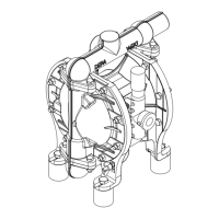
Air Operated Diaphragm Pumps
must wear ear
defenders.
above 85 dB (A): Room with dangerous
noise level! Each door
must have a clearly
noticeable warning sign
to warn persons from
entering the room
without ear defenders.
Measured mean sound pressure level
Lp [dB(A)] acc. to DIN EN 29614-2 (ISO
9614-2) in 1m distance with a pump head
of 60 m, pump DL50-FA-NNN, control air
7 bar, medium water, 20 °C = 66.8 dB(A).
Withadierentpumpratingandpumpsize
or other application related conditions the
mean sound pressure level may deviate.
3.0 Installation
3.1 To be observed before
installation
1 The installation must only be carried out
by persons who have the necessary skills
forthiswork(seechapter2“Safety”).
2 Before installation align the pump
correctly and fasten it without any
tension. Pipelines must be assembled in
a way that the basic weight of the lines is
not reasting on the pump.
3 In order to avoid damage to the pump new
installations should generally be checked
for any debris (welding beads, pieces of
wire, etc.) in tank and pipeline system.
4 Consider the arrangement of the pump
with respect to suction and discharge
heads.
5 The pump system must be designed
according to the requirements of the
application.Valvesorspoolsmust
be installed as close as possible to
pressure port.
ThisalsoappliesforT-ttingswithvalve
for bypass control or pressure relief
valves,pressuregauges,owcontrol
valvesandshut-ovalves.
6 Thoroughlyexaminethealignmentofthe
pump with the pipelines, in order to avoid
strain and premature wear.
7 Check all pipelines for leaks. This applies
in particular for the suction line, in order
to avoid the intake of air.
8 Iftheuidtobepumpedcontainssolid
particlesbiggerthanspeciedinTable
1inSection1.4.4),altermustbe
installed.Theltermustbeofsucha
size, that the change in resistance at the
pumpinletportisonlyminor.Thislter
must be permanently monitored and
cleaned if necessary. Insert a suction
basket.
9 Fluids which change their viscosity must
be permanently agitated, or the tank must
bettedwithatemperaturesensor.With
increasing viscosity start the agitator
and/or the heating. This is of special
importance for intermittent operation!
10 Retighten the clamps bands on pump
and pulsation dampener before initial
start-up.ThetorquesspeciedonPage
45mustbeobserved.
3.2 Design and arrangement of
connecting lines
Byexperience,thecrosssectionofthe
pipelinesmustbedesignedtoallowaow
velocity of 1 to 3 m/s in the pressure line and
0.5 to 1.5 m/s in the suction line (see Section
9.0 for pump connection sizes).