20
DEPA
®
Air Operated Diaphragm Pumps
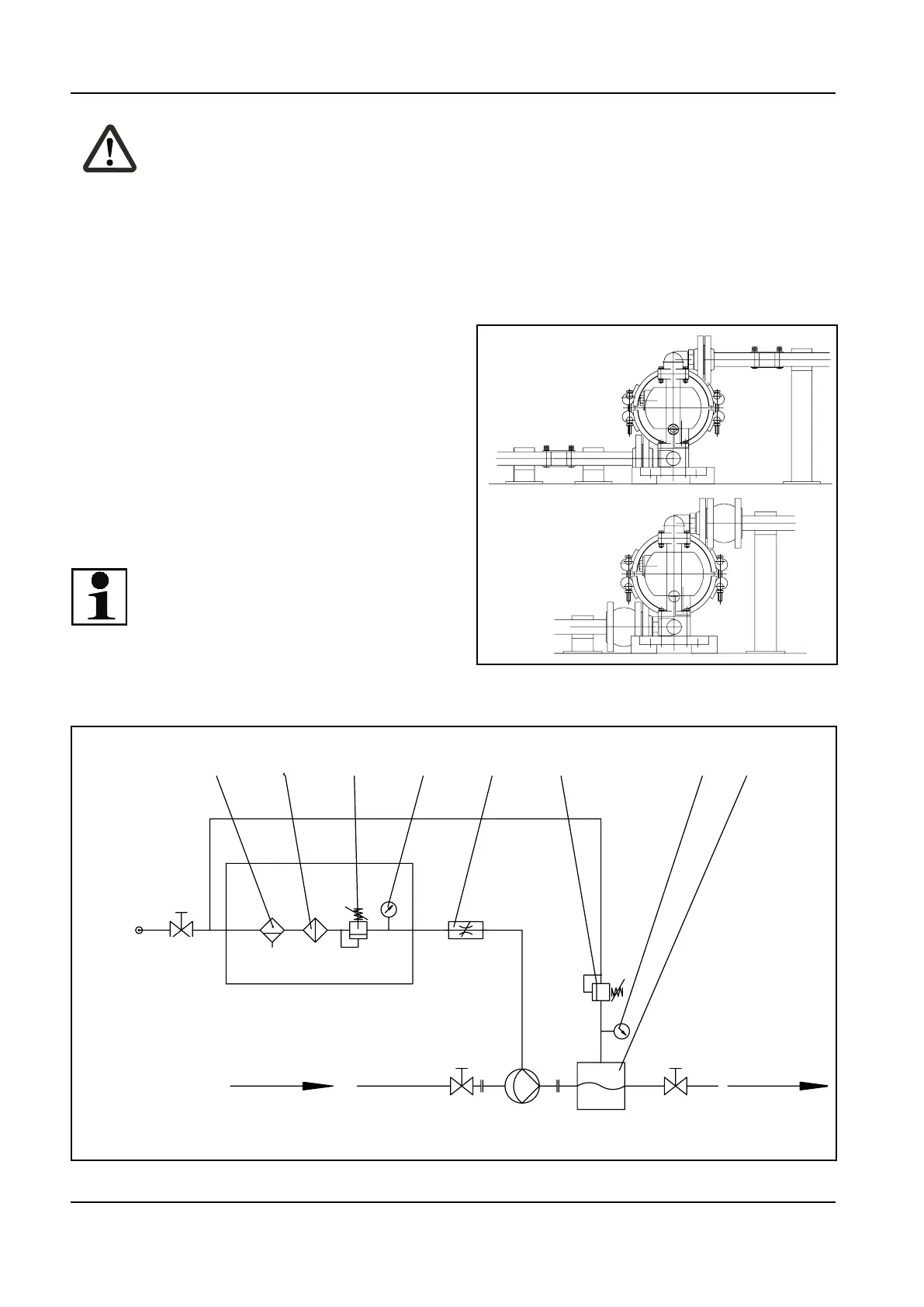
Fig. 3: Installation proposal for diaphragm pump
1
1
2
2
2
2
1. Compensators
2. Pipeline support
Pumping combustible liquids.
Experience has shown that
dangerous charges are not
likely at ow velocities > 7m/s
(TRGS 727).
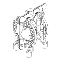
The cross-section of the compressed
air supply must not be smaller then the
connection on the pump.
For simple removal of the pump a shut-
oelementeachmustbeinstalledinthe
suction and pressure sides.
■ The weight of the pipeline must be
taken up before the pump.
■
Elongation compensators must be
installed to compensate any elongation
of the pipes caused by temperature
increase.
Note:
It is recommended to
install flexible, shape and
pressure resistant hoses or
1
2
34
5
364
77
Luft-
versorgung
Einlass
Auslass
aktiver Pulsationsdämpfer
Nadelventil
Druckanzeige
Druckminderer
Filter
Abscheider
3
5
4
6
1
2
Saug- und druckseitige Absperrorgane
7
Inlet
Outlet
1. Water separator
2. Filter
3. Pressure reducer
4. Pressure gauge
5. Needle valve
6. Active pulsation dampener
7. Shut-off elements on suction and
pressure side
Fig. 4: Example of a pump installation
Air
supply
compensators at the suction
and pressure ports of the pump
(Fig. 3). This will prevent the
transfer of pulsation shocks
into the pump.
3.3 Placement and possible
installations of the pump