29
DEPA
®
Air Operated Diaphragm Pumps
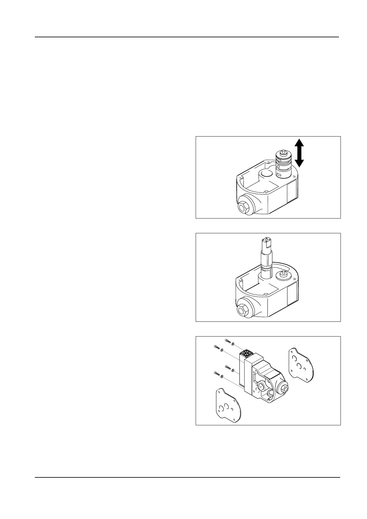
Fig. 17: Assembly of piston rod
Fig. 16: Assembly of internal control valve
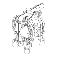
Fig. 18: Assembly of external control valve
ValveseatsforseriesPM(onlyone
O-ring or no O-ring) must be completely
replaced after each disassembly of the
ports.
On plastic pumps from DL25 the O-rings
in the outer diaphragm plate must be re-
placed after each disassembly.
■Assemble the ball lifter (optional acces-
sory), install a pressure-side valve seat
in the ball lifter
■Assemble new valve balls.
■
Tighten the fastening screws for suc-
tion and pressure ports with the correct
torque.
■
Pumps of series DH-TP/TPL are gener-
ally equipped with DEPA nopped E4
®
compound diaphragms. Installation of
the diaphragm takes place by means
ofindexingdiscandsetscrew,without
the diaphragm plate: After the set screw
is threaded, the diaphragm is to be
screwed onto the plunger and tightened
by hand.
5.3.1.4 Replacement of the internal
control valve
■Procedure as described under 5.3.1.
■
Unscrew the air chambers from the
central block (only on metal pumps,
exception:DBdiaphragmpumps,DH)
(Fig. 12).
■
Press the air control valve out of the
central block.
■
The air control valve is replaced as a
complete unit (Fig. 16).
■
To install the plain bearing bushings
and seal ring, we recommend using the
piston rod for guidance (see Fig. 17).
■
In contrast to the assembly instructions
for bearing bushings of pump series
DL25-DL80,whicharettedwithtwo
bearing bushings, the procedure for
pump size DL15 withkits single bearing
bushingisslightlydierent.
The bearing bushing has two grooves
to take up the outer O-rings. In order to