25
DEPA
®
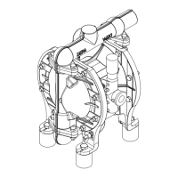
Air Operated Diaphragm Pumps
4.10 Diaphragm break sensors and
shut-down in the event of leaks
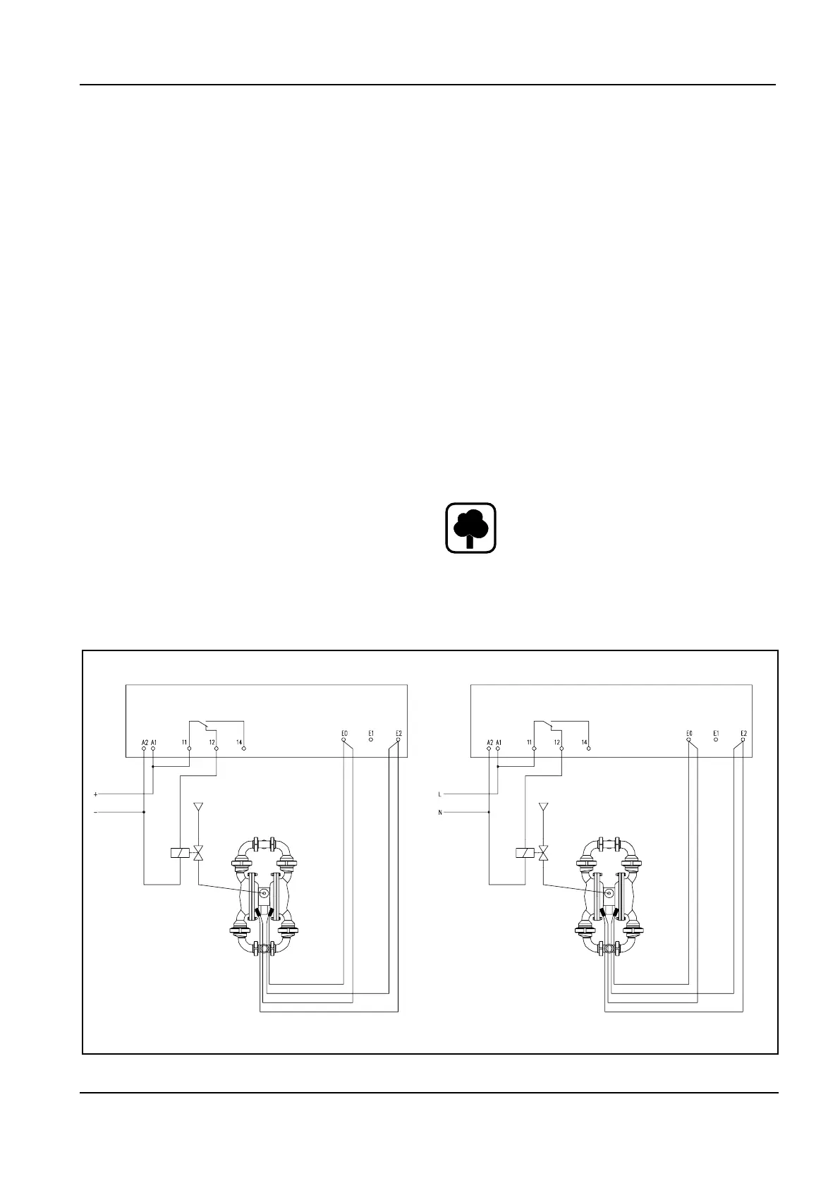
When using diaphragm break sensors, the
air supply may be interrupted if there is a
leak. For electrical connections please refer
to the wiring diagram on page 25 (Fig. 6.
4.11 Pulsation damping
Air operated diaphragm pumps are dou-
ble-acting, oscillating displacement pumps
andthusgenerateapulsatingow.Formin-
imizing this pulsationing we recommend the
use of pulsation dampeners. There are var-
ious designs available, active and passive,
made of metal or plastic, with and without
diaphragmsandinseveraldierentsizes.
Depending on the prevailing pressure condi-
tions they must be manually or automatically
adjusted in-situ. See Fig. 4 and Section 7.
4.12 Downtimes
After pumping product with solids, chem-
icals or oils the pump chambers must be
thoroughlyushedbeforeshuttingdown.
This prevents the settlement of soilds or
chemical attacks and thus the destruction of
the diaphragms when restarting.
4.13 Taking out of service
Thepumpstopswhencuttingotheair
supply. Since the valve balls in suction and
pressure sides act as non-return valves, the
rising part of the pressure line will always
remainlledwithproduct.Whendisassem-
bling the pump care must be taken, as the
pumpmaystillbelledwithproduct.The
pump itself can be partly emptied through
the plugs on the sides of the pump (option-
al).
4.14 Waste disposal after expiry of
the expected service life
The metal components used,
such as aluminium, grey cast
iron, high-grade steel and steel
can be returned for recycling.
Plastic parts cannot be reused
and must be disposed of as
residual waste.
Fig. 6: Wiring diagram leakage sensors
Air supply
Voltage
supply
24VDC
Diaphragm monitoring
Diaphragm monitoring
Voltage
supply
Air supply
Housing width 22.5 mm - suitable for
mountingon35mmopenboxsectionrail
Housing width 22.5 mm - suitable for
mountingon35mmopenboxsectionrail
Wiring diagram
115VAC
(230VAC)