31
DEPA
®
Air Operated Diaphragm Pumps
5.3.2.2 Replacement of diaphragms,
valve seats and valve balls
■ Loosen screws on the suction / pressure
socket
■
Loosen the ball lifter (optional accesso-
ry)
■
Remove the pressure-sided valve balls
and valve seats
■
Remove the suction-sided valve seats
and valve balls
■
Disassemble the pump chambers
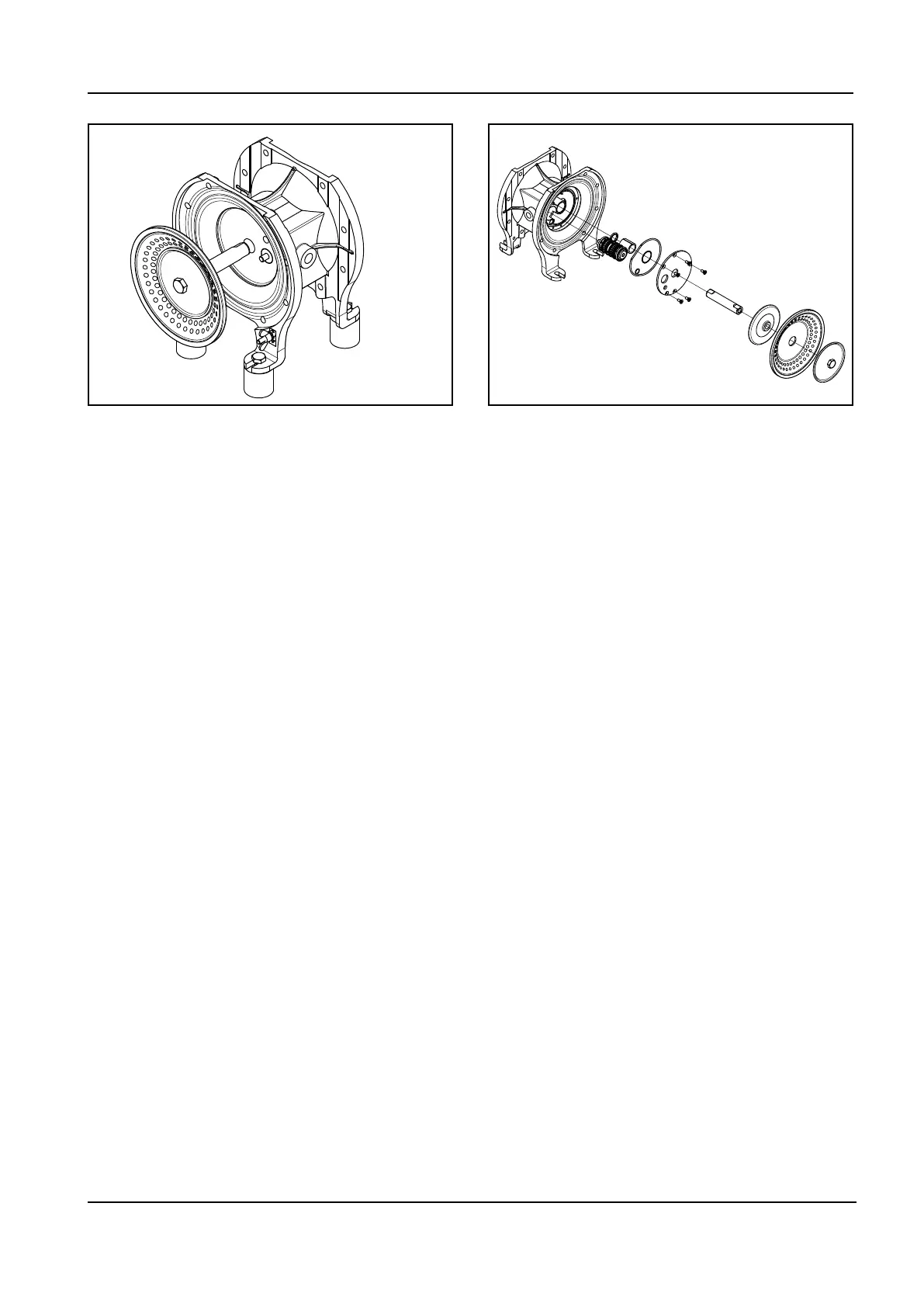
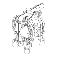
■ Loosen the outer diaphragm plate and
removewiththediaphragm(Fig.10+
Fig. 21).
With nopped E4
®
diaphragms, manually
unscrew the diaphragm directly out of the
piston rod.
■
Pull the piston rod with the second
diaphragm out of the central block and
disassemble the second diaphragm
(Fig. 11).
■
The installation of the new diaphragm,
valve seats and valve balls is done in
reverse order of the above
Information for the material can be found in
Section 5.3.1.1
Fig. 21: Pulling out the diaphragm with piston rod Fig. 22: DH pump with interior control valve
We recommend removing and inspecting the
air control, if the product reach the air area
(see 5.3.2.3).
5.3.2.3 Disassembly of the control block
■
Loosen the suction-/discharge mani-
folds and pump chambers
■ Loosen diaphragm, see Fig. 10 and 21
■
Disassemble the control valve and seal
■ Disassemblethemuer
■ Loosen the control block cover and
remove the seal
■ Push control valve out (interior valve)
■ Push out the switch cartridge (Pilot cont-
rol) (on pumps with AirSave valve)
■
Push out the bearing bush and the ja-
cket ring
■ The assembly is done in reverse order
from the above
5.3.2.4 Replacement of internal valve
■ as described under 5.3.2.3.
■ Insert control valve as complete unit