7.1 12 95-8242
NOTE
Many wiring codes prohibit the connection of a
shield to the negative terminal of a power source
(terminal 2 of the controller). If such a connection
is permitted, the detectors can be wired using a 3
wire shielded cable. The shield is connected to the
“C” terminal of the detector in place of a separate
C-lead. (See Figure 23).
4. Remove the UV sensor tube module from its shipping
package. When handling the sensor tube module,
be careful not to touch the sensor tube, since oil from
the skin can attenuate UV radiation, reducing the
sensitivity of the tube.
IMPORTANT
Use only DE1888 sensor modules with the C7050
Detector. The jumper plug must not be installed
on the UV sensor module used with the R7404
Controller (see Figure 12). The jumper plug is
supplied for detectors that are used with other
controller models.
5. Using the index pin as a guide, install the sensor
module on the detector terminal block.
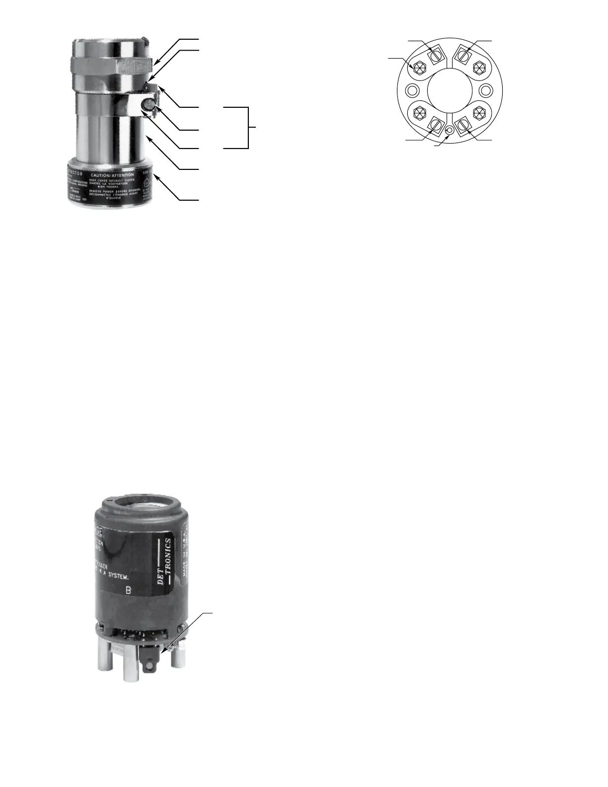
6. Re-assemble the detector housing. If the detectors
are equipped with cover locking devices, loosen the
clamp sufficiently so that the “catch” can be seated
in the blind hole provided on the terminal cap. (See
Figure10.)Theclampmustthenbefastenedsecurely
around the detector barrel by tightening with the
proper tool.
NOTE
If the wires from individual detectors are connected
to the R7404 Controller using a multiple conductor
cable with a single outer shield and without twisted
pairs, careful placement of the individual detector
leads is necessary to prevent “cross-talk” between
zones. The individual B-leads should be arranged
around the outside of the cable with a ground lead
between. The inner layer of conductors should be
the D-leads and the common A-lead should be in
the center.
When using multiconductor cable with twisted
pairs, only one leadwire of each twisted pair can
be connected to the B-terminal in the detector.
The other leadwire must be used as a shield by
connecting it to the C-terminal in the detector and
to ground terminal 2 on the R7404. When several
detectors are connected to one controller using
twisted pairs of leadwires, a junction box is required
to connect the many ground leads together so
that only one ground leadwire need be run to the
controller. (Keep this common ground leadwire as
short as possible.) Ground all unused leads at the
controller. For additional information refer to Service
Memo 75-1003, “Multiconductor Cable Wiring.
B0769
CATCH
BARREL
WINDOW CAP
TERMINAL CAP
BLIND HOLE
CATCH SCREW
STRAP
COVER
LOCKING
ASSEMBLY
Figure 10—Detector with Cover Locking Assembly
Figure 12—Jumper Plug
QUICK CONNECT PLUG (4)
SIGNAL (B)
o
i
FUNCTION (D)
GROUND (C)
+290 VDC (A)
C0125
INDEX PIN
Figure 11—Detector Terminal Block