7.1 11 95-8242
DETECTOR POSITIONING AND DENSITY
The detector has a nominal 90° cone of vision. What this
means in practical terms can be understood by reference
to a typical installation. Consider an application such as
a loading rack with a ceiling height of 25 feet (7.5 meters),
and assume it is desired to have complete detector
coverage at floor level. If a detector is mounted 2 feet
(0.6 meter) from the ceiling and pointed straight down, the
distance from the detector to the designated level would
be 23 feet (7 meters). Because of its 90° cone of vision,
the detector would cover a circular area with a diameter
of 46 feet (14 meters) at the designated level. A simple
layout of the area to be covered will easily reveal the
number of detectors required to completely supervise the
designated area. In general, detectors should be placed
as close as practical to the probable hazard.
NOTE
Do not mount UV detectors close to the ceiling in
enclosed areas if dense smoke can be expected
to accumulate at the onset of a re. Mounting the
detector on side walls a few feet (or about 1 meter)
down from the ceiling will normally allow time for
the detectors to respond before they are affected
by smoke rising to the ceiling. It is also advisable
to shorten any time delay settings for applications
where smoke may accumulate during a re. If
dense smoke can be expected to accumulate prior
to the presence of ame (as in an electrical re), do
not use UV detectors alone.
MOUNTING THE DETECTOR
The following procedure should be used for mounting
and wiring the detectors.
1. Detectors should be located for the best unobstructed
view of the area to be protected. Detectors must
be accessible for cleaning the viewing window and
reflector rings. Care must be taken so that dirt or other
foreign material will not accumulate and obscure the
detector viewing window. For outdoor applications,
the detectors should be pointed downward to prevent
the cone of vision from scanning the horizon, since the
detectors can be affected by long duration lightning
flashes or distant arc welding. When practical,
mount the detectors so that the UV test lamp is on
top, since dirt accumulation between the window and
the reflector ring can interfere with the Automatic o
i
function.SeeFigure4formountingdimensions.
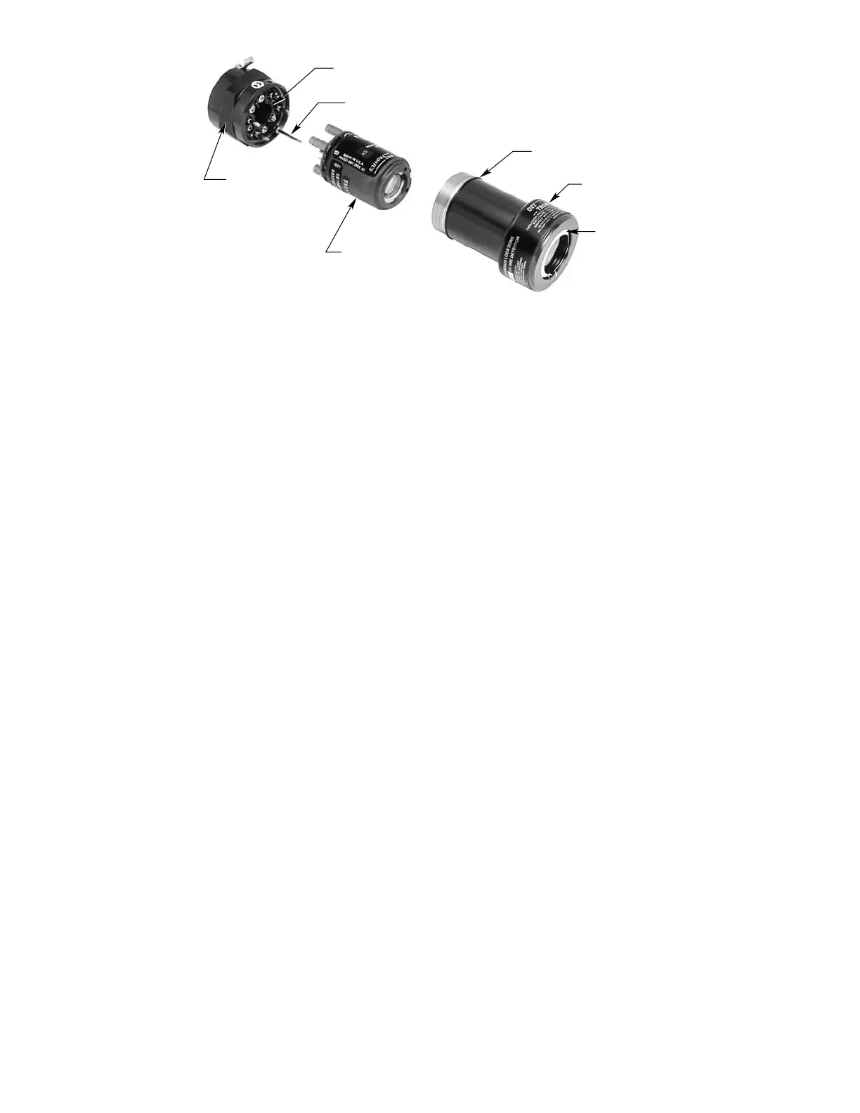
2. Disassemble the detector enclosure by turning the
housing cover counterclockwise. If the detector is
equipped with a cover locking device, loosen the
clamp and disengage the “catch” from the terminal
cap. See Figure 9 for an illustration of the detector
assemblyandFigure10fortheoptionalcoverlocking
assembly.
NOTE
Power must not be applied to the system while
opening the detector housings, or while plugging in
or removing the sensor tube modules.
3. Install the A-, B-, C-, and D-leads to the connections
ontheterminalblock.SeeFigure11.Donotground
the shield to the detector housing.
TERMINAL BLOCK
INDEX PIN
O-RING
WINDOW AND HOUSING
Oi REFLECTIVE RING
UV SENSOR MODULE
TERMINAL CAP
A2078
Figure 9—C7050 Detector