7.1 17 95-8242
TYPICAL SYSTEM APPLICATIONS
The following typical applications are examples only.
SeeFigures22,23and24.Forassistanceinadaptinga
systemtoyourindividualrequirements,contacttheField
Support Group at Detector Electronics.
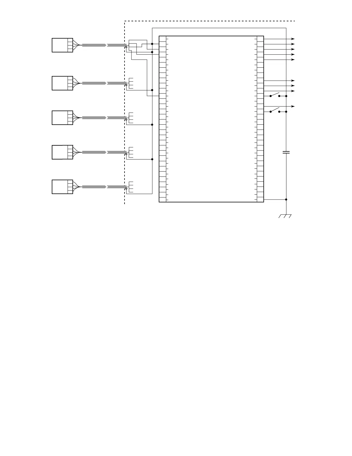
The system illustrated in Figure 22 furnishes solid state
outputsignalsfromzones1to5,FireLogicAandB,and
the Alarm output. External Inhibit and External Accept
are shown connected for use in locations remote from
the controller. Other connections are not used in this
configuration.
External Inhibit/Reset (terminal 44) is a means of remotely
inhibiting the output circuits and resetting the controller.
External Accept (terminal 47) is a means of remotely
turning off the alarm output. These functions can be
performed by a computer interface, external switches, or
any interface that drives the input to less than 0.5 vdc.
Outputs Inhibited (terminal 45) is an output that is driven
low when the controller is in the Outputs Inhibited mode
(keylock switch in TEST or RESET position or External
Inhibit/Reset switch closed).
The system illustrated in Figure 23 furnishes solid state
output signals from zones 1 to 3, Fire Logic A and B,
and the Alarm output. External Inhibit and External
Accept are shown connected for use in locations remote
from the controller. Other connections are not used in
this configuration. In this illustration the detectors are
connected using a 3 wire shielded cable, with the shield
functioning as the C-lead.
NOTE
Wiring codes in many areas do not permit the
detectors to be wired using the method shown in
Figure 23. Therefore, this should be considered an
alternate method for use only where codes allow.
The system illustrated in Figure 24 furnishes solid state
outputsignalsfromzones1through8,FireLogicAand
B, and the Alarm output. External Accept and External
Inhibit are shown connected for use in locations remote
from the controller. Other connections are not used in this
configuration.
1
2
3
4
5
6
7
8
9
10
11
12
13
14
15
16
17
18
19
20
21
22
23
24
25
26
27
28
29
30
31
32
+
–
(A) +290 VDC
B - INPUT 1
B - INPUT 2
B - INPUT 3
B - INPUT 4
B - INPUT 5
B - INPUT 6
B - INPUT 7
B - INPUT 8
D1-1 o
i
DRIVER
D1-2 o
i
DRIVER
D1-3 o
i
DRIVER
D1-4 o
i
DRIVER
D1-5 o
i
DRIVER
D1-6 o
i
DRIVER
D1-7 o
i
DRIVER
D1-8 o
i
DRIVER
D2-1 o
i
DRIVER
D2-2 o
i
DRIVER
D2-3 o
i
DRIVER
D2-4 o
i
DRIVER
D2-5 o
i
DRIVER
D2-6 o
i
DRIVER
D2-7 o
i
DRIVER
D2-8 o
i
DRIVER
DMA OUT AVAILABLE
DMA OUT
DMA IN
DATA STROBE
DMA IN AVAILABLE
33
34
35
36
37
38
39
40
41
42
43
44
45
46
47
48
49
50
51
52
53
54
55
56
57
58
59
60
61
62
63
64
ZONE OUTPUT 1
ZONE OUTPUT 2
ZONE OUTPUT 3
ZONE OUTPUT 4
ZONE OUTPUT 5
ZONE OUTPUT 6
ZONE OUTPUT 7
ZONE OUTPUT 8
FIRE LOGIC “A”
FIRE LOGIC “B”
ALARM OUTPUT
EXTERNAL RESET/INHIBIT
OUTPUTS INHIBITED
FAULT OUTPUT
EXTERNAL ACCEPT
STATUS & DET. OUTPUT S1
STATUS & DET. OUTPUT S2
STATUS & DET. OUTPUT S3
STATUS & DET. OUTPUT S4
STATUS & DET. OUTPUT S5
STATUS & DET. OUTPUT S6
STATUS & DET. OUTPUT S7
STATUS & DET. OUTPUT S8
DATA BUS 0
DATA BUS 1
DATA BUS 2
DATA BUS 3
DATA BUS 4
DATA BUS 5
DATA BUS 6
DATA BUS 7
CHASSIS (EARTH) GND
A
B
C
D
C7050
ZONE 1
A
B
C
D
C7050
ZONE 2
A
B
C
D
C7050
ZONE 3
A
B
C
D
C7050
ZONE 4
A
B
C
D
C7050
ZONE 5
FIRE ALARM CONTROL CABINET
A
B
C
D
A
B
C
D
J1-3
J1-7
J1-2
J1-15
A
B
C
D
J1-3
J1-5
J1-2
J1-13
A
B
C
D
J1-3
J1-6
J1-2
J1-14
A
B
C
D
J1-3
J1-8
J1-2
J1-16
D0285
0.47 uf, 250 VDC
NON-POLARIZED
J2
R7404J1
10 TO 38 VDC
}
Figure 22—Typical System - Five Detectors in Five Zones