7.1 18 95-8242
Status and detector output terminals 48 to 55 provide
binary output representations of the front panel digital
displays for zone, detector, and system status. Tables
3 and 4 list the identification codes and the logic states
ofthe“Fault”and“OutputsInhibited”bitsforthevarious
status conditions.
Under “normal” (no fault) conditions,the Faultoutput is
energized (logic 1).
The Data Bus terminals (56 to 63) and the DMA (direct
memory access) and Data Strobe terminals (28 to 32)
provide external access to the microprocessor, which
permits inter-controller communication. For further
information,contacttheFieldSupportGroupatDetector
Electronics. (This feature is only available on R7404
models with Remote Surveillance, Nuclear Surveillance
and STAR Logic.)
STARTUP PROCEDURE
CAUTION
Placing the controller in the Test mode inhibits
its outputs, rendering the system incapable of
actuating any extinguishing or alarm circuits that
are connected to it. For maximum safety, however,
secure output loads (remove power from any devices
that would normally be actuated by the system)
before manually testing the system. Remember to
place this same equipment back into service when
the test is complete.
1. After setting the selection switches and making all
electrical connections, plug the controller into the
connector.
2. Turn on power and perform Checkout Procedure.
3. If the controller appears to be operating normally,
remove mechanical blocking devices and restore
power to the extinguishing loads.
1
2
3
4
5
6
7
8
9
10
11
12
13
14
15
16
17
18
19
20
21
22
23
24
25
26
27
28
29
30
31
32
+
–
(A) +290 VDC
B - INPUT 1
B - INPUT 2
B - INPUT 3
B - INPUT 4
B - INPUT 5
B - INPUT 6
B - INPUT 7
B - INPUT 8
D1-1 o
i
DRIVER
D1-2 o
i
DRIVER
D1-3 o
i
DRIVER
D1-4 o
i
DRIVER
D1-5 o
i
DRIVER
D1-6 o
i
DRIVER
D1-7 o
i
DRIVER
D1-8 o
i
DRIVER
D2-1 o
i
DRIVER
D2-2 o
i
DRIVER
D2-3 o
i
DRIVER
D2-4 o
i
DRIVER
D2-5 o
i
DRIVER
D2-6 o
i
DRIVER
D2-7 o
i
DRIVER
D2-8 o
i
DRIVER
DMA OUT AVAILABLE
DMA OUT
DMA IN
DATA STROBE
DMA IN AVAILABLE
33
34
35
36
37
38
39
40
41
42
43
44
45
46
47
48
49
50
51
52
53
54
55
56
57
58
59
60
61
62
63
64
ZONE OUTPUT 1
ZONE OUTPUT 2
ZONE OUTPUT 3
ZONE OUTPUT 4
ZONE OUTPUT 5
ZONE OUTPUT 6
ZONE OUTPUT 7
ZONE OUTPUT 8
FIRE LOGIC “A”
FIRE LOGIC “B”
ALARM OUTPUT
EXTERNAL RESET/INHIBIT
OUTPUTS INHIBITED
FAULT OUTPUT
EXTERNAL ACCEPT
STATUS & DET. OUTPUT S1
STATUS & DET. OUTPUT S2
STATUS & DET. OUTPUT S3
STATUS & DET. OUTPUT S4
STATUS & DET. OUTPUT S5
STATUS & DET. OUTPUT S6
STATUS & DET. OUTPUT S7
STATUS & DET. OUTPUT S8
DATA BUS 0
DATA BUS 1
DATA BUS 2
DATA BUS 3
DATA BUS 4
DATA BUS 5
DATA BUS 6
DATA BUS 7
CHASSIS (EARTH) GND
A
B
C
D
C7050
ZONE 1
A
B
C
D
C7050
ZONE 2
A
B
C
D
C7050
ZONE 3
A
B
C
D
C7050
A
B
C
D
C7050
FIRE ALARM CONTROL CABINET
A
B
C
D
A
B
C
D
J1-3
J1-5
J1-2
J1-21
A
B
C
D
J1-3
J1-4
J1-2
J1-20
A
B
C
D
J1-3
J1-5
J1-2
J1-13
A
B
C
D
J1-3
J1-6
J1-2
J1-22
D0286
J2
R7404J1
10 TO 38 VDC
}
A
B
C
D
C7050
A
B
C
D
J1-3
J1-6
J1-2
J1-14
0.47 uf, 250 VDC
NON-POLARIZED
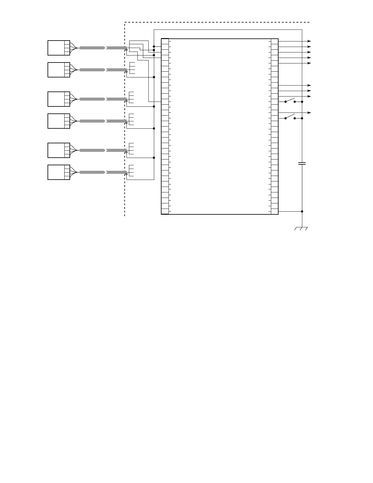
Figure 23—Typical System - Six Detectors in Three Zones