7.1 15 95-8242
4. Output Latching/Non-latching — Rocker 4-1
closed — non-latching
open — latching
NOTE
The zone and re logic outputs will latch when
turned on if rocker 4-1 is set open. The outputs
are de-latched by placing the keylock switch in the
RESET position.
5. Time Delay — Rockers 4-2 to 4-6
The output signals can be delayed as follows:
4-2 closed — 0.5 second
4-3 closed — 1 second
4-4 closed — 2 seconds
4-5 closed — 4 seconds
4-6 closed — 8 seconds
The total time delay is the added value of all closed
rockers. Rockers can be closed in any combination
for a time delay from 0 to 15.5 seconds in half second
increments.Fornotimedelay,allrockersmustremain
open.
Figure18showstheswitchsettingforatimedelayof
6 seconds.
System Layout
When the proper position for each of the rocker switches
has been determined, record this information carefully in
thespaceprovidedontheSystemLayoutChart(Figure
19). This chart is intended as an aid in system layout,
and also provides both a means of double checking
rocker switch positions before power is applied to the
controller and a record of rocker switch positions for
future reference.
Electrical Connections
All electrical connections are made to the field wiring
connectorthatisfurnishedwiththecontroller.Figure20
shows the terminal configuration for the controller.
8
7
6
5
4
3
2
OPEN
NOTE: THE VALUE OF ROCKERS SET IN THE CLOSED POSITION ARE ADDITIVE
A0282
8 SECOND TIME DELAY
4 SECOND TIME DELAY
2 SECOND TIME DELAY
1 SECOND TIME DELAY
0.5 SECOND TIME DELAY
}
NOT USED
ROCKER 5 CLOSED = 4 SECONDS
ROCKER 4 CLOSED = 2 SECONDS
TOTAL TIME DELAY = 6 SECONDS
Figure 18—Time Delay Setting
4
3
2
1
OPEN
3-1 CLOSED = 8 CPS
3-2 CLOSED = 16 CPS
TOTAL SENSITIVITY = 24 CPS
SWITCH 3
A0281
Figure 15—Controller Sensitivity Setting
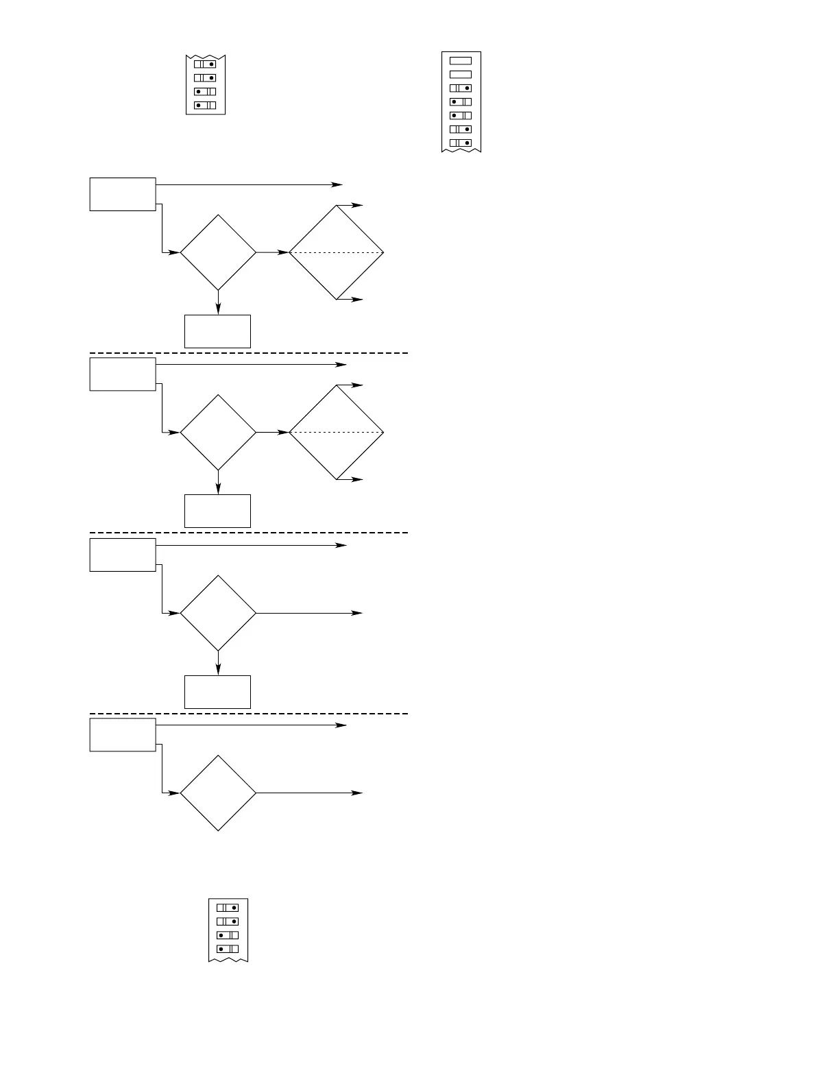
NO
NO FIRE LOGIC
OUTPUT
ANY ONE OR
MORE ZONES
SEE FIRE
ONE ZONE
SELECTED?
B0288
ONE OF
FOUR
ZONES SELECTED
YES
ONE OF EIGHT
ZONES
SELECTED
FIRE
LOGIC
SELECTED
ZONE OUTPUT(S)
FIRE LOGIC
OUTPUT
A OR B
FIRE LOGIC
OUTPUT
A AND B
NO
NO FIRE LOGIC
OUTPUTS
ANY TWO OR
MORE ZONES
SEE FIRE
TWO ZONES
SELECTED?
TWO OF
FOUR
ZONES SELECTED
YES
TWO OF EIGHT
ZONES
SELECTED
ZONE OUTPUTS
FIRE LOGIC
OUTPUT
A OR B
FIRE LOGIC
OUTPUT
A AND B
NO
NO FIRE LOGIC
OUTPUTS
ANY THREE OR
MORE ZONES
SEE FIRE
THREE ZONES
SELECTED?
YES
ZONE OUTPUTS
FIRE LOGIC
OUTPUT
A AND B
ANY FOUR OR
MORE ZONES
SEE FIRE
FOUR ZONES
SELECTED?
YES
ZONE OUTPUTS
FIRE LOGIC
OUTPUT
A AND B
Figure 16—Fire Logic Flow Chart
8
7
6
5
3 OF 8 ZONES VOTING
SWITCH 3
A0280
OPEN
Figure 17—Fire Logic Setting