7.1 4 95-8242
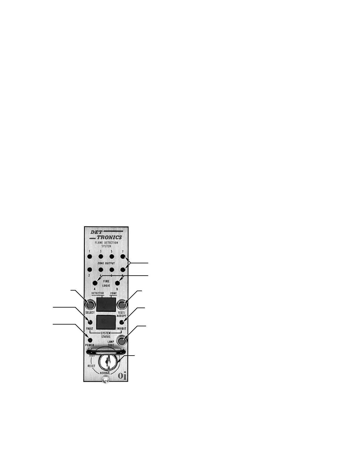
checked for operation by pressing the LAMP TEST button
located directly opposite the POWER light as illustrated in
Figure2.Itisnotnecessaryforthecontrollertobeinthe
TEST mode when this check is performed.
The R7404 Controller incorporates a microprocessor and
a programmable-read-only-memory (PROM) to store
and implement the permanent program for operating
the system. The main loop of the operating program
continuously cycles through the Automatic Optical
Integrity test, checking each detector and its wiring. At
the same time, the microprocessor can be interrupted by
any one of several status changes, such as a fault, a “fire”
signal from one of the detection zones, or a change in
the setting of the keylock switch. In the event of a status
change, the microprocessor will take the appropriate
action.
NOTE
The R7404 is available with various optional operating
programs (STAR Logic, Remote Surveillance, etc.).
This manual covers the operation of the R7404 with
the standard program. Always refer to the manual
supplied with any special purpose controllers when
operating or installing the equipment.
Fire Response
When the controller receives a “fire” signal from any
detector in the system, it is compared to the stored
information of the program. If the signal frequency is lower
than the programmed setting for sensitivity, the lower
display on the front panel of the controller responds with a
“3” and the upper display identifies the first zone affected.
If the signal frequency is greater than the programmed
sensitivity setting for a period greater than the preset time
delay, the following actions take place:
1. The appropriate solid state zone output(s) is energized.
One zone output is available for each of the eight
zones.
2. The solid state alarm output is energized. The alarm
output is activated when any zone detects a fire.
3. TheZONEdisplayidentiestherstrespondingzone.
The DETECTOR display is blank.
4. The SYSTEM STATUS display shows a “6”, indicating
fire.
5. OneormoreZONELEDsturnon(blinking),indicating
the zone(s) detecting UV radiation.
6. If the selected “voting” criteria has been satisfied, the
appropriate Fire Logic output is energized, and the
corresponding LED is on.
NOTE
When a re signal is no longer present, the ZONE
LED(s) and the display indication will latch until
manually reset (ZONE LED emits steady light). The
display latch feature is useful in post-re analysis as
a means of determining re origin.
The Alarm output is typically used to actuate an external
audible alarm when a fire signal is received from one or
more detectors. Since these alarms can be disruptive to
personnel who are responding to the fire emergency, a
means for alarm silencing has been provided. The R7404
is equipped with a TEST/ACCEPT button, which will de-
activatethealarmcircuitwithoutinterruptingtheZoneand
FireLogicoutputs.Thealarmcanalsobesilencedbyan
optional external silence switch (see “Typical Applications”
section).
NOTE
If the system is going to be put out of service for
periods of time, use the Test/accept to bypass
the alarm contacts instead of shutting down the
system. This will provide optimum performance
when reconnected.
E0235
RED LEDS
RED LEDS
KEYLOCK SWITCH
LAMP TEST
TEST/ACCEPT
AMBER LED
DETECTOR SELECTION
AMBER LED
GREEN LED
Figure 2—Front Panel of R7404