2
© 2001
© 35 583 0
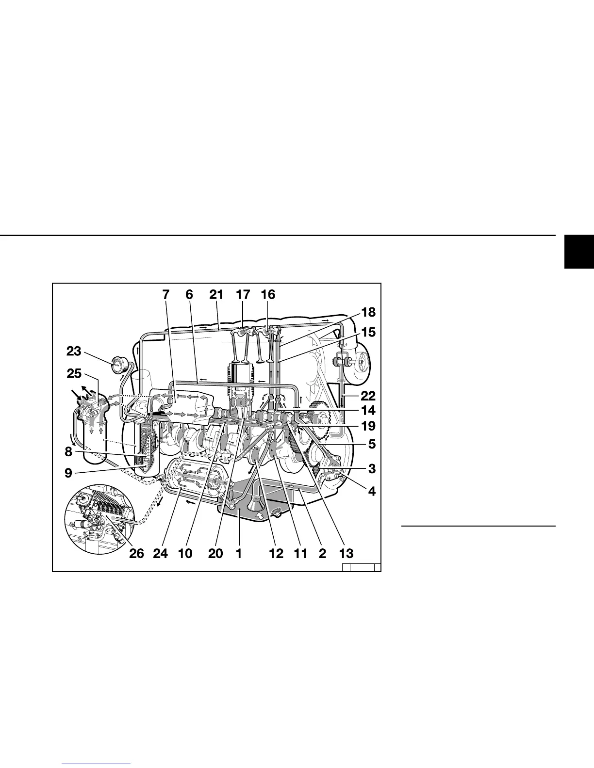
2.3 Lube Oil Circuit Schematic Engine Description
1 Oil pan
2 Intake line
3 Oil pump
4 Oil pressure regulating valve
5 Pressure oil line
6 Connection line to oil cooler
7 Block oil cooler
8 Lube oil filter
9 Safety valve
10 Main oil channel
11 Crankshaft bearing
12 Con-rod bearing
13 Camshaft bearing
14 Tappet (with impulse lubrication of rocker
arm)
15 Pushrod (hollow, for oil intake to lubricate
rocker arm)
16 Rocker arm bearings
17 Rocker arm lubrication
18 Pushrod protective tube (oil return from the
cylinder head to crankcase)
19 Throttle bore (to lubricate cogwheels)
20 Spray nozzle for piston cooling
21 Oil line to lubricate turbocharger
22 Oil return line from exhaust turbocharger
to crankcase
23 Oil pressure gauge
24 Bypass lube oil fine filter
25 Connection option for oil heater **
26 Injection pump connected to lube oil circuit
schematic
** here the filter carrier must be exchanged.
Please contact DEUTZ Service when
changing-over.
2.3.2 Lube Oil Circuit Schematic
BFL 914