11
MG6-OLVERT-3B Rev. 0 12/30/99
Drain Valve: At the base of the air tank to drain condensa-
tion at the end of each use.
ON/AUTO-OFF Switch: Turn this switch ON to provide
automatic power to the pressure switch and OFF to remove
power.
Pressure Switch: The pressure switch automatically starts
the motor when the air tank pressure drops below the factory
set "cut-in" pressure. It stops the motor when the air tank
pressure reaches the factory set "cut-out" pressure.
Air Intake Filter: This filter is designed to clean air coming
into the pump. This filter must always be clean and ventila-
tion openings free from obstructions. See "Maintenance".
Air Compressor Pump: In two stage compressors, air is first
compressed to an intermediate pressure in the large bore
cylinder, and after passing through an intercooler, the air is
further compressed to a higher pressure in the smaller bore
cylinder. This process continues until the air tank pressure
reaches the factory set cutoff pressure. At that point the
pressure switch shuts the electric motor off.
Check Valve (not shown): When the air compressor is
operating, the check valve is "open", allowing compressed air
to enter the air tank. When the air compressor reaches "cut-
out" pressure, the check valve "closes", allowing air pressure
to remain inside the air tank.
Pressure Release Valve (not shown): The pressure release
valve located on the side of the pressure switch, is designed
to automatically release compressed air from the compressor
DESCRIPTION OF OPERATION
head and the outlet tube when the air compressor reaches
"cut-out" pressure or is shut off. If the air is not released, the
motor will try to start, but will be unable to. The pressure
release valve allows the motor to restart freely. When the
motor stops running, air will be heard escaping from the
valve for a few seconds. No air should be heard leaking when
the motor is running.
Shut-off Valve: Turn the knob counterclockwise to open the
valve and clockwise to close. (if equipped)
Air Tank Safety Valve: If the pressure switch does not shut
off the air compressor at its cut-out pressure setting, the
safety valve will protect against high pressure by "popping
off" at its factory set pressure (slightly higher than the
pressure switch cut-out setting).
Aftercooler Safety Valve (not shown): On two stage
compressor units, safety valve is provided to prevent over-
pressurization of the aftercooler. The valve will protect the
aftercooler by "popping off" at its factory set pressure.
Tank Pressure Gauge: The tank pressure gauge indicates
the reserve air pressure in the tank. On outfits with no
pressure regulator, this is also the pressure available at the air
outlet.
Regulator (sold separately): An air pressure regulator or a
separate air transformer which combines the functions of air
regulation and/or moisture and dirt removal is recommended
for most applications.
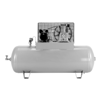
Air Intake Filter
Magnetic Starter
(if equipped)
2-Stage Air
Compressor
Pump
Electric Motor
Shut-Off Valve
Tank Pressure Gauge
Air Tank Safety Valve
ON/AUTO-OFF Switch
Pressure Switch
Drain Valve
NOTE: Photographs and line drawings
used in this manual are for reference
only and do not represent a specific
model.