15
MG6-OLVERT-3B Rev. 0 12/30/99
Belt - Replacement
(Refer to the Outfit Parts Manual for replacement
belt part number.)
SERIOUS INJURY OR DAMAGE MAY OCCUR IF
PARTS OF THE BODY OR LOOSE ITEMS GET
CAUGHT IN MOVING PARTS. NEVER OPERATE
THE OUTFIT WITH THE BELT GUARD REMOVED.
THE BELT GUARD SHOULD BE REMOVED ONLY
WHEN THE COMPRESSOR POWER IS DISCON-
NECTED.
1. Turn compressor off, lock out the power supply, and relieve
all air pressure from the tank.
2. Remove the clips, screws, and outer panel of belt guard.
3. Loosen the motor mounting hardware and slide the motor
toward the compressor.
4. Remove the belt and replace with a new one.
Safety Valve - Inspection and Replacement
IF THE SAFETY VALVE DOES NOT WORK PROP-
ERLY, OVER-PRESSURIZATION MAY OCCUR
CAUSING AIR TANK RUPTURE OR EXPLOSION.
OCCASIONALLY PULL THE RING ON THE SAFETY
VALVE TO MAKE SURE THAT THE SAFETY VALVE
OPERATES FREELY. IF THE VALVE IS STUCK OR
DOES NOT OPERATE SMOOTHLY, IT MUST BE
REPLACED WITH A VALVE HAVING THE SAME
PRESSURE RATING.
1. Remove and lock out power from the compressor. Release
any air pressure from the air tank.
2. Remove safety valve and replace with valve of the same
pressure rating.
3. Apply thread sealant to new safety valve and tighten. DO
NOT OVERTIGHTEN.
SAFETY VALVE
SERVICE INSTRUCTIONS (cont'd)
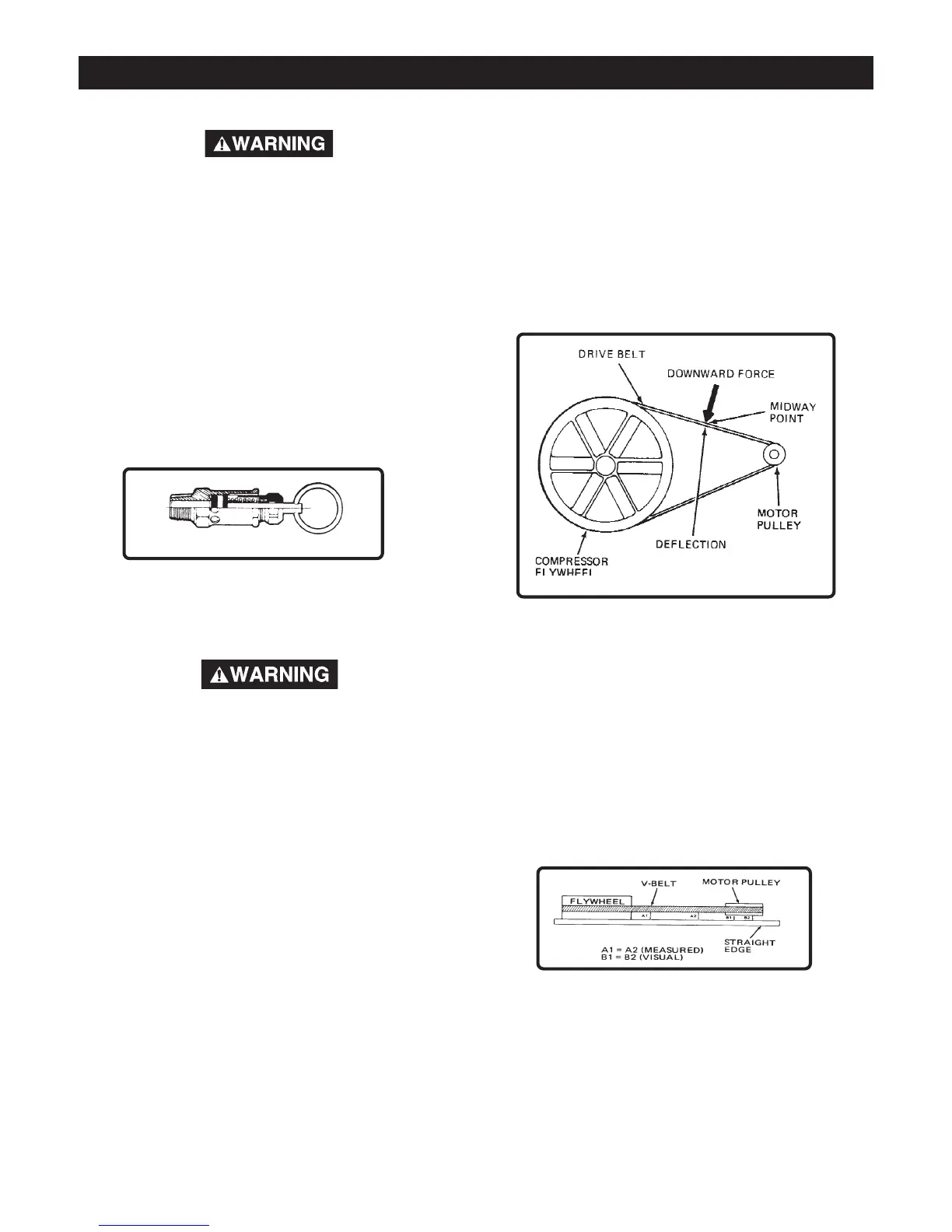
Adjusting Belt Tension
Adjust belt tension as described below:
1. Slide motor away from compressor until desired tension is
obtained.
The belt should deflect 3/16" at midway between the pulley
and the flywheel when a 5 pound weight is applied at the
midway point.
2. Tighten two outside cap screws enough to hold the motor
in place for checking pulley and flywheel alignment.
3. Once aligned, tighten all four cap screws. See Outfit Parts
Manual for correct torque specifications.
Motor Pulley and Flywheel Alignment
1. Place a straight edge along the outside face of the compres-
sor flywheel to check alignment of V-belt grooves. (See
figure below for proper alignment.)
2. If the belt grooves aren't aligned, continue with step 3 of this
procedure. If the belt grooves are aligned, continue with step
4 of this procedure.
3. Loosen pulley set screw and move the pulley until it is in
proper alignment.
4. Tighten pulley set screw. See Outfit Parts Manual for correct
torque specifications.
5. Reinstall belt guard.