EN - 5SE-DV54-1
• DonotplacetheSleepCubewhereitcanbeknockedontotheoororwherethepowercordmaycreateatrip
hazard.
• OnlytheDeVilbissDV5seriesHeatedHumidiersystemisrecommendedforusewiththeSleepCube.Other
humidiersystemsmaypreventthedevicefromdetectingsnoringandmaycauseinappropriatepressurelevelsin
the mask.
• Emptyanddryhumidierwaterchamberbeforetransporting.
INTRODUCTION
Intended Use
TheDeVilbissSleepCubeModelDV54SeriesAutoAdjustisintendedforuseintreatingOSAinspontaneouslybreathing
patients 30 Kg (66 lbs) and above by means of application of positive air pressure. The Device is to be used in home and
clinical environments.
Indications For Use (Optional Heated Humidifier)
Use on the advice and prescription of a licensed physician to help relieve the symptoms of dryness of the throat, nasal
passages and the mouth, which are common with positive airway pressure therapy. This is especially true in dry climates
and during the cold season when humidity in the air is typically lower than at other times.
Contraindication
Do not use SleepCube system if your upper airway has been bypassed.
NOTE–Symptoms of dryness of the throat, nasal passages, and the mouth are common with positive airway pressure
therapy. The SleepCube features an optional humidier system to help minimize these effects.
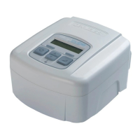
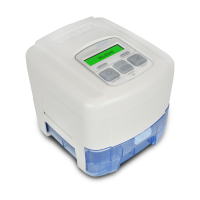
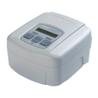
KEY FEATURES (Page 2, Figures A-F)
DeVilbiss SleepCube Device (Figures A
and B)
1. Keypad/LCD Display (see Figure C)
2. Air Supply Port on Back
3. AirSupplyPortonBottom(foroptionalhumidier)
4. Air Supply Port Plug
5. HeaterPowerConnector(foroptionalhumidier)
6. AC Power Connector
7. DC Power Connector
8. Data Port
9. Power Cord (appropriate to your wall outlet) (not
shown)
10. Air Inlet Filter Opening
11 Connector Cover (not shown)
Keypad (Figure C)
1. On/Off
2. Previous Item
3. Next Item
4. Delay
5. Decrease Value
6. Increase Value
7. Heater PowerLED(foroptionalhumidier)
Ask your equipment provider for information about other
DeVilbiss masks, equipment, and accessories.
Humidifier Cradle (Figure D)
1. Heater plate
2. Heater power connector
3. Storage compartment for connector cover (on
bottom)
4. Air supply port inlet
5. Air supply port outlet
6. Flow generator release button
7. Flow generator locking tabs
Water Chamber (Figure E)
1. Chamber lid
2. Chamber base
3. Heat transfer plate (on bottom)
4. Sealing gasket
5. Water level indicators (front and sides)
6. Chamber release latch
7. Chamber disassembly lever
Therapy Management System
(Figure F)
1. SmartLink
®
(optional)
SYSTEM ASSEMBLY
Without Heated Humidification
1. Locate the air supply port and heater power connector on the bottom of the SleepCube device. Ensure that each
opening has the appropriate soft cover securely attached.
2. Place the SleepCube on a stable surface such as a nightstand or table. If you wish, you may also place the device
ontheooratthebedside,beingcarefultoplacetheunitwhereitwon’tbekickedorsteppedon.Ensurethattheair
inlet in the back of the device is not blocked by anything such as curtains or bedding.
NOTE
–Never place the SleepCube system on a soft surface such as a bed or couch during operation.