10
English
FIG. 16
FIG. 17
FIG. 18
A.
B.
ANGLE “A”
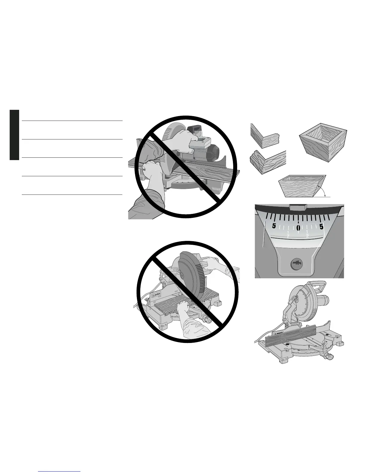
FIG. 19
MITER
SCALE
FIG. 20
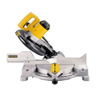
IMPROPER HAND POSITION
IMPROPER HAND POSITION
BEVEL SETTING TYPE OF CUT
LEFT SIDE, INSIDE CORNER:
33.85° 1. Top of molding against fence
2. Miter table set right 31.62°
3. Save left end of cut
RIGHT SIDE, INSIDE CORNER:
33.85° 1. Bottom of molding against fence
2. Miter table set left 31.62°
3. Save left end of cut
LEFT SIDE, OUTSIDE CORNER:
33.85° 1. Bottom of molding against fence
2. Miter table set left 31.62°
3. Save right end of cut
RIGHT SIDE, OUTSIDE CORNER:
33.85° 1. Top of molding against fence
2. Miter table set right 31.62°
3. Save right end of cut
When setting bevel and miter angles for all compound
miters, remember that:
The angles presented for crown moldings are very
precise and difficult to set exactly. Since they can easily
shift slightly and very few rooms have exactly square
corners, all settings should be tested on scrap molding.
PRETESTING WITH SCRAP MATERIAL IS EXTREMELY
IMPORTANT!
ALTERNATIVE METHOD FOR CUTTING CROWN
MOLDING
Place the molding on the table at an angle between the fence
and the saw table, as shown in Figure 25A. Use of the crown
molding fence accessory (DW7084) is highly recommended
because of its degree of accuracy and convenience. The
crown molding fence accessory is available at extra cost
from your local dealer.
The advantage to cutting crown molding using this method
is that no bevel cut is required. Minute changes in the miter
angle can be made without affecting the bevel angle. This
way, when corners other than 90 degrees are encountered,
the saw can be quickly and easily adjusted for them. Use
the crown molding fence accessory (DW7084) to maintain
the angle at which the molding will be on the wall.
INSTRUCTIONS FOR CUTTING CROWN MOLDING
ANGLED BETWEEN THE FENCE AND BASE OF
THE SAW FOR ALL CUTS:
1. Angle the molding so the bottom of the molding (part
which goes against the wall when installed) is against
the fence and the top of the molding is resting on the
base of the saw, as shown in Figure 25A.
2. The angled “flats” on the back of the molding must rest
squarely on the fence and base of the saw.
FIG. 15A
 Loading...