English
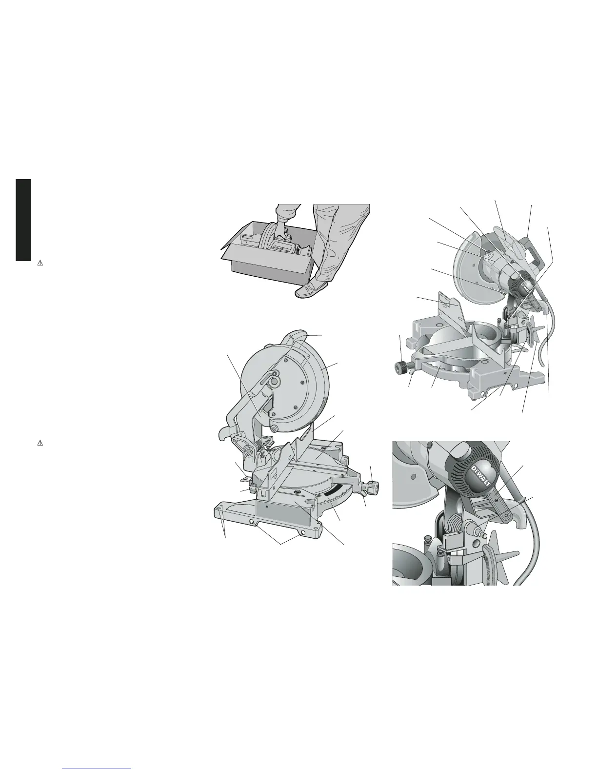
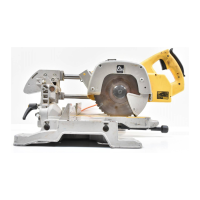
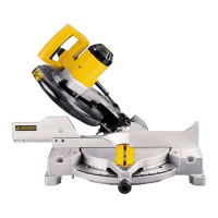
FIG. 3
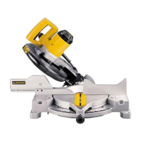
FIG. 4
LOCK
DOWN
PIN
TRIGGER
SWITCH
CARRYING
HANDLE
SPINDLE
LOCK
BUTTON
LEFT
SIDE
FENCE
MITER
CLAMP
KNOB
MOTOR
HOUSING
REAR
GUARD
BEVEL
STOP
BEVEL
SCALE
MITER
LATCH
MITER
SCALE
HAND
INDENTATION
BEVEL CLAMP
KNOB
DUST
SPOUT
MOTOR
END CAP
4
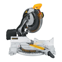
FIG. 1
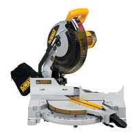
FIG. 2
GUARD
RIGHT
SIDE
FENCE
MITER
CLAMP
KNOB
MITER
LATCH
MITER
SCALE
BENCH
MOUNTING
HOLES
LEFT SIDE
FENCE
CLAMPING
KNOB
REAR
GUARD
OPERATING
HANDLE
TABLE
BASE
BLADE
WRENCH
HOLES FOR
EXTENSION KIT
STABILIZER
BAR
Stabilizer
Your saw includes a stabilizer (Fig.2). This must be in
place and in contact with the work surface at all times
while using your saw. This stabilizer is factory installed
and needs no adjustment.
Accessories
Recommended accessories for use with your tool are
available at extra cost from your local retailer or
authorized service center.
CAUTION: The use of any non-recommended
accessory such as dado sets, molding cutters, or abrasive
wheels may be hazardous.
If you need assistance in locating any accessory, please
contact D
EWALT Industrial Tool Co., 701 East Joppa
Road, Baltimore, MD 21286 or call 1-800-4-D
EWALT (1-
800-433-9258).
Bench Mounting
Holes are provided in all four feet to facilitate bench
mounting, as shown in Figure 2. (Two different sized holes
are provided to accommodate different sizes of screws.
Use either hole, it is not necessary to use both.) Always
mount your saw firmly to prevent movement. To enhance
the tool’s portability, it can be mounted to a piece of 1/2"
or thicker plywood which can then be clamped to your
work support or moved to other job sites and reclamped.
NOTE: If you elect to mount your saw to a piece of
plywood, make sure that the mounting screws don’t
protrude from the bottom of the wood. The plywood must
sit flush on the work support. When clamping the saw to
any work surface, clamp only on the clamping bosses
where the mounting screw holes are located. Clamping at
any other point will surely interfere with the proper
operation of the saw.
CAUTION: To prevent binding and inaccurate cuts, be
sure the mounting surface is not warped or otherwise
uneven. If the saw rocks on the surface place a thin piece
of material under one saw foot until the saw sits firmly on
the mounting surface.
Installing a New Saw Blade
(UNPLUG THE MITER SAW)
DO NOT CUT FERROUS METAL (THAT WITH AN IRON
OR STEEL CONTENT) OR MASONRY WITH THIS
MITER SAW.
With the saw arm in the upper position, raise the blade
guard as far as possible. Loosen (but do not remove) the
guard bracket screw, shown in Figure 5 until the guard
bracket can be raised enough to permit access to the
blade screw. The blade guard will be held in the raised