4
English
S
FIG. 6
Z
Y
T
I
T
I
ATTACHING THE STORAGE FOOT (FIG. 7)
1. With stand right side up, place the storage foot (C) over the
indentations of the wheel and storage-foot connector (N) so when
the stand is right side up the storage foot will angle upward.
2. Turn stand upside down and align the holes in storage foot and
storage foot connector. Install two M8 x 15 mm button head
screws (L) with curved washers (M) to attach storage foot and the
connector.
3. Tighten screws securely with the supplied hex wrench.
4. Securely tighten the storage-foot connector screws that were
loosely installed in Attaching the Wheel and Storage Foot
Connector.
NOTE: Do not overtighten. Overtightening may cause wheel
rotation to be impaired.
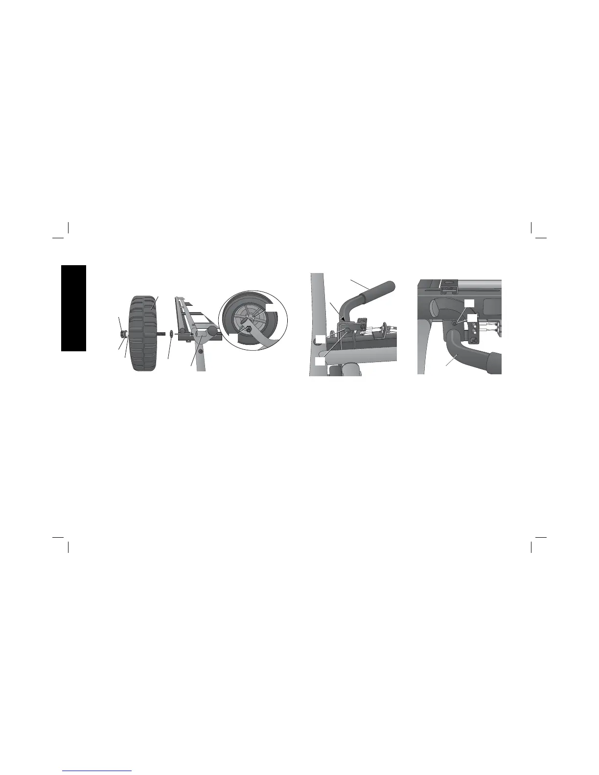
3. Attach the other wheel in the same manner.
FIG. 5
P
Q
U
Q
O
R
MM
D
ATTACHING THE HANDLE (FIG. 6)
1. With stand upside down, attach the handle (I) on the end of the
stand opposite the wheels with one M8 x 20 mm button head
screw (S) and lock washer (Z). Install screw using supplied hex
wrench, but DO NOT tighten securely.
2. Turn the stand right side up so the wheels and leg extension sit
level on the floor
or stable table. Ensure the stand remains in the
closed position, do not raise the stand.
3. Install one M6 x 10 mm button head screw (T) and lock washer (Y)
on the other side. Tighten securely with the supplied hex wrench.
4. Tighten M8 x 20 mm button head screw (S) added in STEP 1
securely with the supplied hex wrench.