29
DE-M040302E • DEWE-5000 • Technical Reference Manual • Printing version 2.2.3 • January 19, 2012
Main System
Power supply backplane / cooling fan
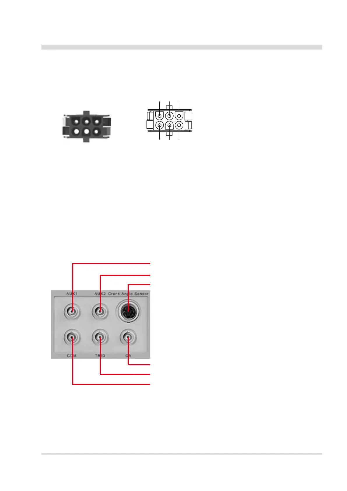
The AMP connector is the internal power supply connection to the internal rack and the cooling fan, mounted
on the backplane of the DEWE-5000 system.
Pin assignment
1: +12 V
2: GND
3: not connected
4: -12 V
5: GND (EPAD supply)
6: +12 V (EPAD supply)
6-pin AMP connector Schematic
Digital I/O connector
This connector supports digital input and output lines of the built-in A/D board. If this board does not support
digital I/O’s, the connector is not available.
The pin assignment is depending on the used A/D board - details are available in appendix B.
Ground connectors
For some kind of measurements, it’s necessary to give the system an additional ground connection.
Combustion Analyzer I/O connectors (DEWE-5000-CA)
The Combustion Analyzer requires several special input signals to work. Please refer to appendix B (wirings)
for details.
‘Zero position’ signal (upper death point signal), TTL level input
CDM - angle position signal from high resolution encoders, TTL level input
CA Connector
Signal output 1 (wiring according to appendix B)
Crank Angle Sensor
Signal output 2 (wiring according to appendix B)