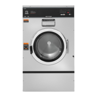
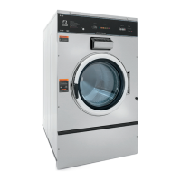
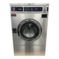
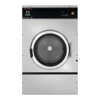
This document is a Parts & Service Manual for the Dexter O-Series OPL Express Plus Washers, specifically models WN0675, WN0975, and WN1475 (Express Plus Washers 400G), starting from serial number W1.
The Dexter O-Series OPL Express Plus Washers are industrial laundry machines designed for on-premise laundry (OPL) applications. These washers are engineered for durability and efficient operation, offering a 400G extract force for effective water removal, which contributes to reduced drying times and energy consumption. The machines are designed to be permanently installed appliances and require connection to an individual branch circuit for electrical supply.
Important Safety Warnings and Symbols:
The manual emphasizes safety with various symbols and terminology:
- DANGER: Indicates an imminently hazardous situation that will result in death or serious injury if not avoided.
- WARNING: Indicates a potentially hazardous situation that could result in death or serious injury if not avoided.
- CAUTION: Indicates a potentially hazardous situation that may result in minor or moderate injury if not avoided, or alerts against unsafe practices.
- NOTICE: Provides information or company policy related to personnel safety or property protection.
- User Caution Symbol: Indicates conditions where equipment damage or operator injury could occur if operational procedures are not followed.
- Electrical Hazard Symbol: Warns of dangerous high voltages present inside the enclosure and advises servicing by qualified personnel only.
- Sharp Edges Caution: Alerts users to sharp edges within the enclosure.
- Water Inlet Valve Caution: Warns against supplying inlet water exceeding 70°C to prevent damage.
- Fire/Explosion Caution: Prohibits operation in hazardous (ATEX) classified environments.
- Door Glass Warning: Do not operate if door glass is damaged.
- Rotating Parts Warning: Keep clear of rotating parts.
- Prohibited Entry: Do not enter the equipment or space.
- Prohibited Standing: Do not step or stand on the equipment.
- Guards/Covers Warning: Do not operate without all guards and covers in place.
- Flammable Liquids Prohibition: Do not wash clothing impregnated with flammable liquids (petrochemical).
- Children Safety: Do not allow children to play in or around the equipment.
- Prohibited Opening: Do not attempt to open, touch, or proceed before referring to the manual or unless qualified.
- Mandatory Documentation: Read all supporting documentation before operating or maintaining.
- Mandatory Power Disconnect: Disconnect power before servicing.
- Mandatory Lock Out/Tag Out: Lock out and tag out before servicing.
- Mandatory Water Disconnect: Disconnect water supply before servicing.
- Mandatory Children Supervision: Children should be supervised to ensure they do not operate equipment.
Important Technical Specifications:
The washers are available in 208-240 volts, 60Hz, and can be configured for single-phase or three-phase power.
- T-675 (WN0675XB-12EO): 40 lb (18.1 kg) dry weight capacity, 993 RPM extract speed, 350 G-force.
- T-975 (WN0975XB-12EO): 60 lb (27.2 kg) dry weight capacity, 969 RPM extract speed, 400 G-force.
- T-1475 (WN1475XB-12EO): 90 lb (40.8 kg) dry weight capacity, 816 RPM extract speed, 350 G-force.
Foundation and Mounting:
- Washers must be installed on or over bare concrete floors, not combustible flooring.
- Securely bolted and grouted to a substantial concrete floor or base.
- Foundation work must ensure a stable unit to eliminate excessive vibration.
- Requires reinforced concrete floors and quality grade anchor bolts or expansion anchors.
- Pedestal options are available to elevate the machine for easier loading access (e.g., 4 inches for T-675/975/1475 models).
- Grouting is essential after concrete cures, with specific instructions for leveling and tightening anchor nuts.
Electrical Connections:
- Single/three-phase 208-240VAC 60 Hz (single phase 230VAC 50 Hz) non-heated models and three-phase only 208-240VAC 60 Hz (400VAC 50 Hz) heated models.
- Permanent installation, no power cord provided.
- Individual branch circuit required, not shared with other equipment.
- Means for disconnection with at least 1/8” (3 mm) contact separation.
- Liquid-tight or approved flexible conduit for connections.
- Control transformer must be set to the proper tap for 208-240V (60Hz) or 180-255V (50Hz) operation.
- Grounding screw next to the power terminal block must be connected to a good external ground.
- Transient voltage surge suppressors are recommended to protect electrical components.
Plumbing:
- ¾-11 ½ NHT for 60 Hz models and ¾-14 BSP for 50 Hz models for water supply hoses.
- Separate hot and cold water lines required, maintaining 30-120 psi (207-827 kPa) flow pressure.
- Recommended hot water supply of 140°F (60°C), not to exceed 180°F (82°C).
- Drain outlet tube size: 3 inches (76 mm) for T-650, T-750, T-950, and T-1450. Drain hose must be lower than the drain valve.
Usage Features:
- DexterLive Programming: Cycles are programmed via DexterLive.com, allowing customization of wash cycles, stages, and settings.
- Cycle Customization: Up to 20 unique stages per cycle, with adjustable parameters such as bath temperature (Hot, Warm, Cold, No Fill), water level (Low, High), soap/chemical injection type, delay, and duration.
- Agitation Types: Normal, Delicate, and 3 custom agitation types with adjustable tumble speed, tumble time, and dwell time.
- Emergency Stop Button: Ends the cycle, drains water, and allows door opening after a delay.
- Safety Door Lock: Locks the door during operation and for up to 3 minutes after power interruption.
- Variable Frequency Drive (VFD) Indicators: LEDs (READY, RUN, FAULT) on the VFD for troubleshooting.
- Delay Fill: Delays stage timer until low water level is met, ensuring proper soak/agitation times.
- Delay Spin: Reduces nuisance Slow Drain error codes in slow drain situations.
Maintenance Features:
- Top Panel Removal: For access to the detergent dispenser and control trough.
- Front Panel Removal: For access to internal components.
- Back Panel Removal: Provides access to the rear of the machine, also contributes to cabinet rigidity.
- Drain Valve Access & Cleaning: Instructions for removing and cleaning the ball-type drain valve.
- Detergent Dispenser Access: For cleaning and maintenance.
- Vacuum Breaker: Located in the left rear of the cabinet, guides water to the tub and dispenser and prevents backflow.
- Water Valves: Removal and disassembly instructions for dual outlet and single coil valves, including checking inlet screens.
- Door Lock Assembly Adjustment: Procedures for adjusting the door cam, switch actuation, and lock pawl.
- Loading Door Adjustment: Instructions for adjusting shims and hinge bolts to ensure proper fit and sealing pressure.
- Cylinder (Basket) Removal & Reassembly: Detailed steps for removing and reinstalling the cylinder, including pulley, hub, and shaft.
- Bearing Housing Assembly Removal & Reassembly: Instructions for replacing bearings and seals.
- Outer Tub Removal: Steps for removing the outer tub after other components are detached.
- Drive Belt Removal: Instructions for removing and installing the drive belt.
- Control Panel Name Plate Decal: Removal and re-installation.
- Control Mounting Trough: Access to control PCBs, transformers, and pressure switch.
- Main Data Communication Cable: Connection between front PCB and VFD.
- Circuit Breaker/Fuse: Location and replacement instructions.
- Main Control Printed Circuit Board & Main Relay Printed Circuit Board: Removal instructions.
- LED Printed Circuit Board Temperature & Start Display/Push-Button: Location and re-installation notes.
- Pressure Switch: Description of function and location.
- Power Connection Terminal Block: Location for incoming power connections.
- Delta Variable Frequency Drive: Description of connections and dynamic braking resistors.
- Delta VFD Cooling Fan: Operation and safety notes.
- Preventative Maintenance Schedule:
- Daily: Check door lock, clean cabinet, clean soap dispenser, check for door leaks, leave door open when not in use.
- Quarterly: Shut off power, check V-belts, clean lint from motor, check water connections, check drain valve, clean inside of washer, remove/clean water inlet hose filters, check anchor bolts.