www.dfi .com
17
Chapter 2 Hardware Installation
Chapter 2
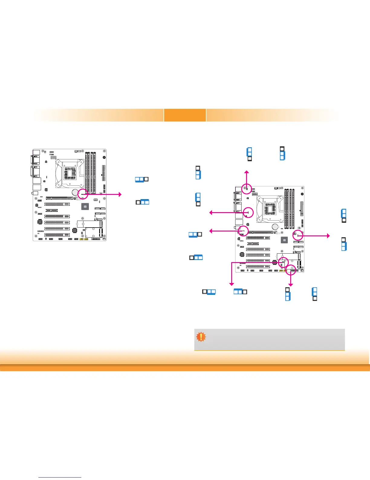
Clear CMOS Data
If you encounter the followings,
a) CMOS data becomes corrupted.
b) You forgot the supervisor or user password.
you can reconfigure the system with the default values stored in the ROM BIOS.
To load the default values stored in the ROM BIOS, please follow the steps below.
1. Power-off the system and unplug the power cord.
2. Set JP5 pins 2 and 3 to On. Wait for a few seconds and set JP5 back to its default setting,
pins 1 and 2 On.
3. Now plug the power cord and power-on the system.
2-3 On:
Clear CMOS Data
1-2 On:
Normal (default)
312
312
A61
Battery
A61
JP5
JP12, JP13, JP14, JP15, JP16 and JP20 are used to select the power of the USB ports. Select-
ing +5VDU will allow you to use a USB device to wake up the system.
USB Power Select
2-3 On: +5V
1-2 On:
+5VDU (default)
Important:
If you are using the Wake-On-USB Keyboard/Mouse function for 2 USB ports, the
+5V_standby power source of your power supply must support ≥1.5A. For 3 or more
USB ports, the +5V_standby power source of your power supply must support ≥2A.
3
1
2
3
1
2
1
3
2
1
3
2
A61
Battery
A61
USB 2.0 5-6
(JP20)
USB 3.1 1-2
(JP12)
USB 3.1 5-6
(JP16)
312
312
1-2 On:
+5VDU (default)
1-2 On:
+5VDU (default)
2-3 On: +5V
2-3 On: +5V
2-3 On: +5V
1-2 On:
+5VDU (default)
312
312
USB 3.1 3-4
(JP13)
3
1
2
3
1
2
1-2 On:
+5VDU (default)
2-3 On: +5V
USB 2.0 7-8
(JP14)
1
3
2
1
3
2
1-2 On:
+5VDU (default)
2-3 On: +5V
USB 2.0 9&14
(JP15)
 Loading...