www.dfi .com
28
Chapter 2 Hardware Installation
Chapter 2
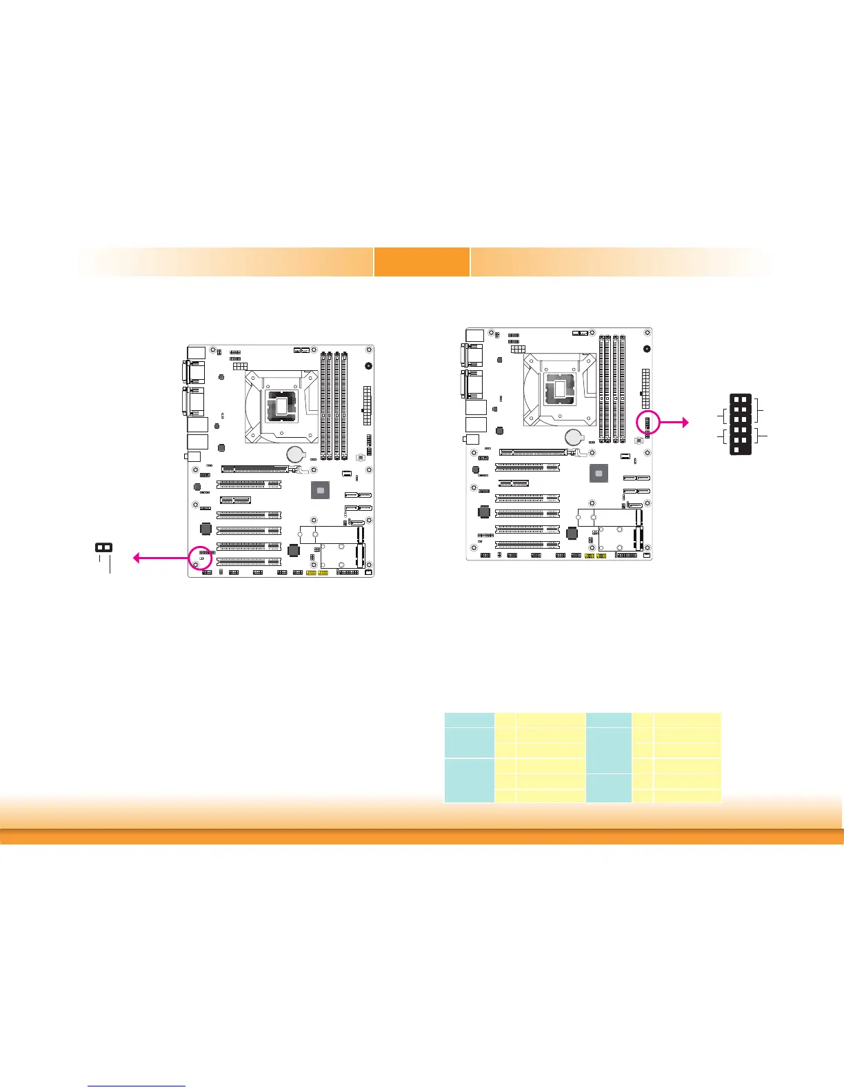
Chassis Intrusion Connector
The board supports the chassis intrusion detection function. Connect the chassis intrusion
sensor cable from the chassis to this connector. When the system’s power is on and a chassis
intrusion occurred, an alarm will sound. When the system’s power is off and a chassis intrusion
occurred, the alarm will sound only when the system restarts.
BIOS Setting
Configure the chassis intrusion detection function in the Advanced menu (“SIO NUVO-
TON6106D” submenu) of the BIOS. Refer to the chapter 3 for more information.
12
Ground
Signal
Chassis
Intrusion
A61
Battery
A61
Front Panel Connector
HD-LED
RESET
PWR-LED
ATX-SW
1211
21
Front
Panel
A61
Battery
A61
HD-LED - Hard Drive LED
This LED will light when the hard drive is being accessed.
RESET - Reset Switch
This switch allows you to reboot without having to power off the system.
PWR-LED - Power/Standby LED
When the system’s power is on, this LED will light. When the system is in the S1 (POS - Power
On Suspend) state, it will blink every second. When the system is in the S3 (STR - Suspend To
RAM) state, it will blink every 4 seconds.
ATX-SW - ATX Power Switch
This switch is used to power on or off the system.
Pin Pin Assignment Pin Pin Assignment
HD-LED
3 HDD Power
PWR-LED
2 LED Power
5 Signal 4 LED Power
RESET
7 Ground 6 Signal
9 RST Signal
ATX-SW
8 Ground
11 N.C. 10 Signal
 Loading...