EasyManua.ls Logo

Dh-Robotics PGC-50 - User Manual

Dh-Robotics PGC-50
24 pages
Print Icon
To Next Page IconTo Next Page
Loading...
Tel/Fax: 0755-82734836 www.dh-robotics.com
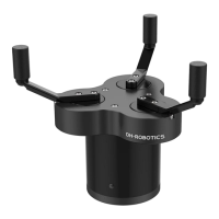
PGC-50 Gripper
Short Manual
Content
Revisions ........................................................................................................................................... 1
1 Specifications ................................................................................................................................. 2
1.1 Performance Parameter ....................................................................................................... 3
1.2 Indicator .............................................................................................................................. 3
1.3 Pinout Description ............................................................................................................... 3
1.4 Product list .......................................................................................................................... 4
2 Modbus-RTU Control .................................................................................................................... 6
2.1 Debugging software description ......................................................................................... 6
2.1.1 Installation and wiring of debugging software ......................................................... 6
2.1.2 Debugging software instructions .............................................................................. 7
2.2 Default Communication Parameters ................................................................................. 10
2.3 Modbus-RTU Description ................................................................................................. 11
2.3.1 RTU Framing ......................................................................................................... 11
2.3.2 Register Mapping ................................................................................................... 11
2.3.3 Register Description ............................................................................................... 12
2.3.3.1 Initialization ................................................................................................ 12
2.3.3.2 Force ............................................................................................................ 13
2.3.3.3 Position ........................................................................................................ 13
2.3.3.4 Speed ........................................................................................................... 14
2.3.3.5 Initialization State ....................................................................................... 15
2.3.3.6 Gripper State ............................................................................................... 15
2.3.3.7 Current Position .......................................................................................... 16
2.3.3.8 Save Parameter ............................................................................................ 16
2.3.3.9 Initialization Direction ................................................................................ 16
2.3.3.10 Slave Address ............................................................................................ 17
2.3.3.11 Baud Rate .................................................................................................. 18
2.3.3.12 Stop Bits .................................................................................................... 18
2.3.3.13 Parity ......................................................................................................... 18
2.3.3.14 I/O Mode Switch ....................................................................................... 19
2.3.3.15 Test I/O Parameters ................................................................................... 20
2.3.3.16 I/O Parameter Configuration ..................................................................... 20
3 I/O Control ................................................................................................................................... 22
Question and Answer IconNeed help?

Do you have a question about the Dh-Robotics PGC-50 and is the answer not in the manual?

Summary

Revisions

Specifications

Performance Parameter

Details the technical specifications and performance metrics of the gripper.

Indicator

Explains the meaning of different indicator light colors and their states.

Pinout Description

Describes the gripper's pin assignments and wire connections.

Product List

Lists the components included in the product package.

Modbus-RTU Control

Debugging Software Description

Introduces the software used for gripper control and parameter setup.

Default Communication Parameters

Lists the default communication settings like Slave Address and Baud Rate.

Modbus-RTU Description

Details the Modbus-RTU protocol structure and message framing.

I;O Control

Input State

Describes the gripper's behavior based on input pin states.

Overview

The PGC-50 Gripper is a three-finger cooperative electric gripper designed for precision machining, parts assembly, and other fields. It features a smooth circular structure with three fingertips evenly distributed on a circle, operating symmetrically during movement. The gripper's base is adapted to a standard flange and includes an 8-core communication interface for connecting to robots or other equipment.

Function Description:

The PGC-50 Gripper offers versatile control and feedback capabilities:

  • Controllable Force/Position/Speed: Users can program and adjust the grip position, grip force, and speed, allowing for precise manipulation of objects.
  • Multiple Communication Modes: The gripper supports Modbus RTU protocol and I/O mode control. For other communication protocols like USB and ETHERNET, a protocol converter can be used.
  • Gripping Detection: The gripping process combines force and position control to ensure effective object handling.
  • Gripping Feedback: The gripper's status can be read programmatically, and its indicator light provides visual feedback on its state.
  • Customizable Fingertips: The fingertips are replaceable, allowing adaptation to various application requirements.

Important Technical Specifications (CGI-100 model):

  • Gripping Force (per jaw): 30-100 N
  • Opening/Closing Stroke (both sides): Ø40-Ø170 mm
  • Opening/Closing Time: 0.5 s / 0.5 s
  • Weight: 1.5 kg
  • Position Repeatability (both sides): ±0.03 mm
  • Noise Emission: < 50 dB
  • Ingress Protection Rating: IP40
  • Communication Protocols: Modbus RTU (RS485), I/O
  • Nominal Voltage: 24 V DC ±10%
  • Nominal Current: 0.4 A
  • Peak Current: 1 A

Usage Features:

The gripper's operation is managed through Modbus RTU control or I/O control, with a dedicated debugging software for configuration and testing.

Modbus RTU Control:

The gripper uses the standard Modbus-RTU protocol for communication, allowing data to be read from and written to its registers.

  • RTU Framing: Messages consist of Slave Address, Function Code, Register Address, Register Data, and CRC for error checking. The default Slave Address is 1, but it can be modified.
  • Register Mapping: Registers are categorized into basic control registers (initialization, force, position, speed) and configuration registers (Modbus communication parameters, I/O parameters).
  • Initialization (Register 0x0100): Writing 1 (0x01 hex) initializes the gripper, moving fingers to minimal or maximal positions based on the initialization direction. Writing 165 (0xA5 hex) performs a full initialization, finding both minimal and maximal positions.
  • Force (Register 0x0101): Sets the gripping force from 20-100%. Exceeding the current limit stops the fingers and triggers object detection.
  • Position (Register 0x0103): Sets the reference position of the gripper's fingers, ranging from 0-1000%.
  • Speed (Register 0x0104): Sets the closing and opening speed of the gripper, ranging from 1-100%.
  • Initialization State (Register 0x0200): Reads the current initialization state (Not initialized, Initialized, Initializing).
  • Gripper State (Register 0x0201): Provides real-time feedback on the gripper's state (In motion, Reached position, Object caught, Object dropped).
  • Current Position (Register 0x0202): Reads the actual current position of the gripper.
  • Save Parameter (Register 0x0300): Writing 1 to this register saves all modified I/O or communication parameters to flash memory. This process takes 1-2 seconds, during which the gripper will not respond to other commands.
  • Initialization Direction (Register 0x0301): Configures whether the gripper opens (0) or closes (1) to find the maximum/minimal position during initialization.
  • Slave Address (Register 0x0302): Sets the Modbus ID of the gripper, allowing control of multiple devices. Default is 1, range 1-247.
  • Baud Rate (Register 0x0303): Configures the Modbus Baud rate (115200, 57600, 38400, 19200, 9600, 4800). Default is 115200 (value 0).
  • Stop Bits (Register 0x0304): Configures the number of stop bits (1 or 2). Default is 1 stop bit (value 0).
  • Parity (Register 0x0305): Configures the parity setting (None, Odd, Even). Default is None (value 0).
  • I/O Mode Switch (Register 0x0402): Turns I/O Control Mode ON (1) or OFF (0). If ON and parameters are saved, the gripper initializes automatically after power-on. In I/O mode, the gripper responds to both Modbus-RTU and I/O commands, with I/O having priority.
  • Test I/O Parameters (Register 0x0400): Allows direct testing of the four groups of I/O parameters configured via Modbus-RTU.
  • I/O Parameter Configuration (Registers 0x0405-0x0410): Configures four groups of I/O parameters, each including position, force, and speed settings. These can be set individually or continuously using function code 0x10.

I/O Control:

The I/O mode is a common industrial control method. The gripper monitors the states of Input 1 and Input 2 (0V and high resistance states), which combine to form four logic states (00, 01, 10, 11). Each state corresponds to one of the four pre-configured I/O parameter groups (position, force, speed).

  • Steps to switch IO mode:
    1. Open IO mode via the debugging software.
    2. Configure the four groups of I/O parameters (position, force, speed).
    3. Click "Save" to write parameters to the internal flash register.
    4. Restart the gripper for the switch to IO mode to take effect.
  • Input State (Table 3.1): Different combinations of Input 1 and Input 2 states (No wiring/0V) trigger specific actions based on the configured parameter groups.
  • Output State (Table 3.2): Output 1 and Output 2 (0V and high resistance states) provide feedback on the gripper's state (Fingers in motion, Fingers at reference position/no object detected/object dropped, Fingers stopped due to object detection, Gripper detects object falling).
  • Digital I/O Default: Default input and output are NPN type, with 0V being valid (low level valid). PNP type (24V effective/high level valid) can be configured upon request.

Debugging Software:

The debugging software facilitates control and parameter setting on a computer. It requires a USB to 485 module to convert the interface, as computers typically lack RS485 ports.

  • Wiring: Connect 24V, GND, 485_A (T/R+), and 485_B (T/R-) wires. The USB port of the module plugs into the computer.
  • Installation: Software and drivers are integrated into the installation process.
  • Instructions: After connecting, open the software, which automatically identifies the serial port, baud rate, and gripper ID for connection. The main control interface allows initialization, demonstration mode, control of position/force/speed, real-time display of clamping status, and parameter setting for Modbus RTU and I/O modes.

Maintenance Features:

  • Parameter Saving: The "Save Parameter" function ensures that any changes to I/O or communication parameters are permanently stored, requiring a restart for full effect.
  • Indicator Lights: The gripper's indicator light provides immediate visual cues for various states:
    • Uninitialized state: Red light blinks, other lights off.
    • Initialized State: Blue light is always on (operable state).
    • Received command state: Red light blinks quickly (appears purple due to blue light being on).
    • Object Caught state: Green light is always on, other lights off.
    • Object dropped state: Green light blinking.
  • Product List: The package includes the PGC gripper, flange, U-disk (for software), screws (M6*12, M4*6), and wrenches (M2.5, M4).
  • Extension Cables: Standard M12 aviation plug wire (8 wires) can be extended with a 5m extension cable. M8 aviation plugs can be customized for cooperative robots with RS485 or I/O interfaces, requiring confirmation of pin definitions with the robot manufacturer and potential extra costs for non-standard configurations.

Dh-Robotics PGC-50 Specifications

General IconGeneral
BrandDh-Robotics
ModelPGC-50
CategoryTools
LanguageEnglish