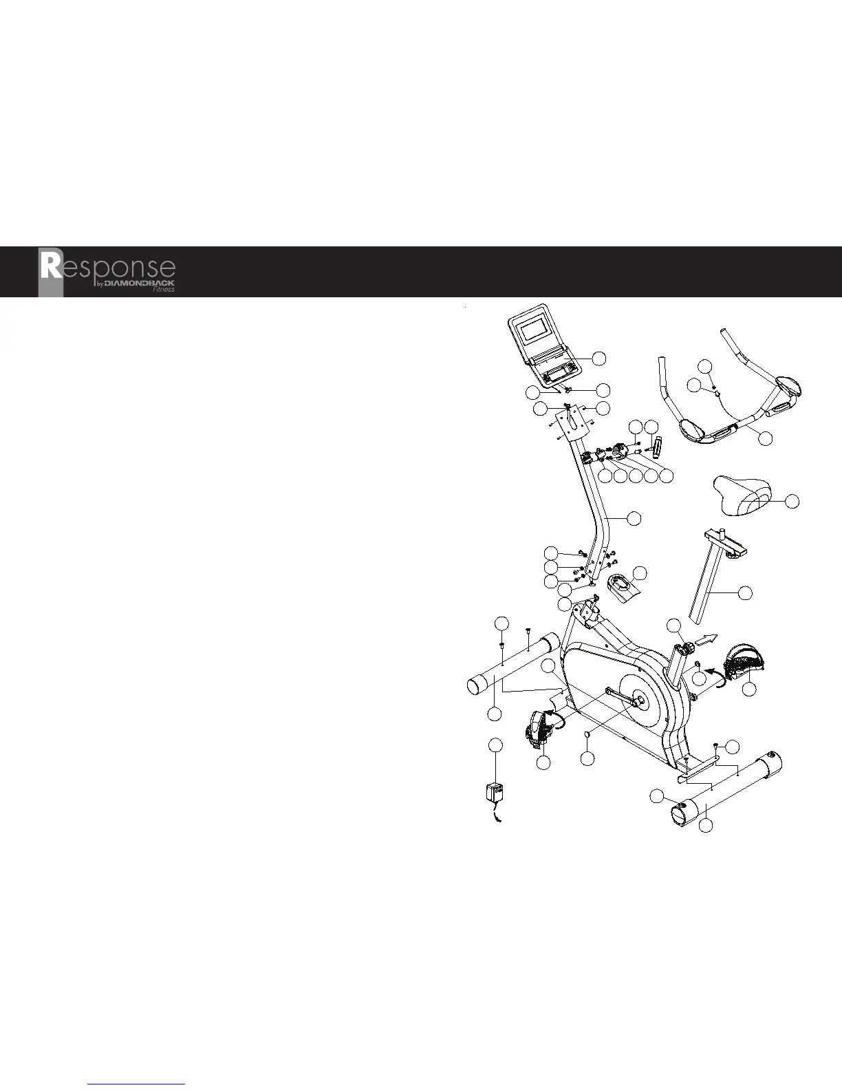
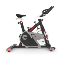
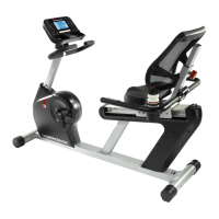
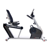
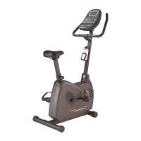
Part Description
A .......Front Stabilizer [Quantity: 1]
B .......Hex Bolt - M8 x 1.25 x 16 mm (6 mm socket) [2]
C .......Rear Stabilizer [1]
D .......Hex Bolt - M8 x 1.25 x 16 mm (6 mm socket) [2]
E1 ......Pedal – Left [1]
E2 ......Pedal – Right [1]
F .......Saddle [1]
G .......Seat Post Assembly [1]
H .......Lower Wire Harness Connector [1]
J .......Console Mast Assembly [1]
K1 ......Upper Wire Harness – Connector 1 [1]
K2 ......Upper Wire Harness – Connector 2 [1]
L .......Curved Washer – 8.0 x 19.0 x 2.0 mm [1]
M.......Flat Washer – 8.0 x 19.0 x 2.0 mm [4]
N .......Hex Bolt – M8 x 1.25 x 12 mm (6 mm socket) 5]
P .......Handlebar Assembly [1]
Q1 ......Handlebar Fixing Clamp [1]
Q2 ......Lock Washer – 7.0 x 13.0 x. 2.0 mm [2]
Q3 ......Flat Washer – 7.0 x 12.0 x 1.0 mm [2]
Q4 ......Handlebar Clamp Cover [1]
Q5 ......Spacer/Bushing – 7.0 x 12.0x 40 mm (plastic) [1]
Q6 ......T-Handle – M7 x 1.0 x 65 mm [1]
Q7 ......Hex Bolt – M7 x 1.0 x 30 mm [1]
R .......Console [1]
S .......Heart Rate Wire Harness – Console [1]
T .......Heart Rate Wire Harness – Handlebar [1]
U .......Rubber Grommet [1]
V .......Wire Harness - Console [1]
W.......Phillips Screw – M5 x 0.8 x 10 mm [4]
X .......AC Adaptor – US Plug; 120V, 60 Hz, 9V, 1A 1]
Y .......Console Mast Cover [1]
Z .......Crank Cap [2]
AA ......Leveling Foot/End Cap [2]
BB ......Seat Post Adjustment Knob [1]
CC......Input Jack [1]
RESPONSE U6c ASSEMBLY
6