5. Turn the faucet on, the controller will open momentarily and then will
shut off.
6. Program the controller. (See #4 – Irrigation Programming)
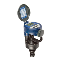
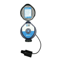
3.3 BATTERY INSTALLATION
1. Holding the upper section of the controller above the mechanical
handle, use a firm upward twist to release the controller from the
skirt.
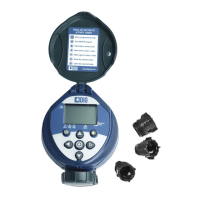
2. Invert the controller and use firm pressure to lift the battery
compartment cover (1)
3. Insert the lower end of the battery (2) first, then press on the top end
(3) to ensure the battery is firmly in place.
Battery Removal
1. Remove the battery compartment cover (4).
2. Lift the lower end of the battery (5) first. If necessary, use the flat end of a small screwdriver.
• Removing the batteries from the top end may damage the connections.
• Use alkaline batteries only.
• Note: battery polarity is marked in the battery compartment.
Replace battery compartment cover in its proper place, ensuring a triangle is formed on the
underside of the controller.
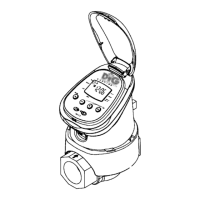
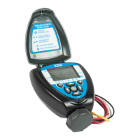
3.4 MANUAL MECHANICAL OPERATION
The irrigation valve can be opened and closed independent of
controller operation. Manual operation is useful when irrigation is
required immediately but there is inadequate time and/or knowledge
for programming or the battery is unavailable. The manual operating
handle is located in the back, lower section of the skirt. It has two
settings: open (1) and automatic (2).
NOTE: The manual operating handle can only open the valve. It
cannot close the valve if the irrigation controller program opened it.
REMEMBER: The manual operating handle must be on automatic
(AUTO) for controller operated irrigation.
5
3.2 FAUCET INSTALLATION
1. First attach the swivel female hose thread by male pipe thread adapter
to the inlet side of the controller, by threading the male side of the
adapter to the controller inlet, see arrow for water flow direction.
(Figure 4)
2. Attach the male hose thread by male pipe thread adapter to the outlet side of the controller by
threading the male pipe thread side of the adapter to the controller (finer thread). (Figure 4)
If vacuum breaker (antisiphon valve) is part of your faucet (new houses) do not install any other
vacuum breaker (antisiphon valve) to the faucet. If vacuum breaker (antisiphon valve) is part of
your city code and you have purchased a unit as part of your drip system, install the device with
the female hose thread to the faucet and the male thread to the swivel adapter (see Figure 5a
and 5b. For pipe thread outlet on the antisiphon, install the controller directly to the antisiphon.
3. Connect the controller to your faucet using the swivel adapter (Figure 5a) or to the vacuum
breaker (antisiphon valve) with hose thread if installed (Figure 5b) DIG Model #10.
4. After installation of the controller, if you use a drip system, first connect the pressure regulator
with hose thread DIG Model #4 to lower the incoming pressure to your drip system and then the
swivel adapter DIG Model #18 and then the drip line. See Figures 6a and 6b.
Drip system installed with filter. See Figures 7a and 7B.
Figure 5b
Figure 6b
Figure 7b
4
Figure 4
Figure 5a
Figure 6a
Figure 7a
Swivel
Adapter
Nipple Hose x Pipe Thread
Backflow
Preventer
#41 Pressure Regulator
with Hose Thread
#18 Swivel Adaptor to
Drip System
#3 Filter
#5 Pressure Regulator
with Pipe Thread
#72 Swivel Adapter
to Drip System