INTRODUCTION
Thank you for purchasing a DIG Controller.
Please take the time to read through the enclosed instructions and follow them step by step. If you
have any questions, please call our customer service line 1-800-344-6641.
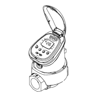
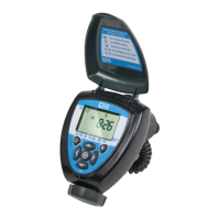
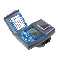
1. PARTS IDENTIFICATION
1) Top cover
2) Controller display
3) Mechanical operating handle
4) Programming & operating buttons
5) Water flow direction
6) Skirt
7) Hydraulic valve
2. SETTING UP THE IRRIGATION CONTROLLER
ASSEMBLY
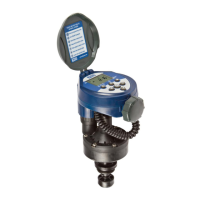
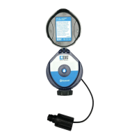
Your 7001 controller has a 3/4" inlet and outlet with female pipe thread
and can be installed in line directly to 3/4" PVC male pipe thread fittings
as part of your sprinkler's valve manifold or as a stand-alone unit. (Fig. 1)
OR
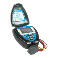
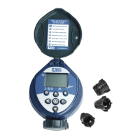
The 7001 controller can be attached to a hose or faucet/spigot using the
two adapters that are included with the controller. (Figure 2)
Warning: Wrap all fittings with Teflon tape! Do not use pipe cement
on valve, this will damage the valve and void the warranty!
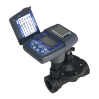
NOTE: The correct installation of the controller is where the orange handle is away from the faucet
and the controller's digital display reading is facing the faucet.
IMPORTANT: Make sure that the flow direction arrow engraved on the side of the controller is
pointed away from the water source.
3. INSTALLATION
3.1 IN-LINE INSTALLATION
1. Shut off main water supply.
2. Install a 3/4" ball or gate valve to a PVC pipe or to
the valve manifold before installing the controller
(Figure 1).
3. Turn water supply on to flush the line and then shut
the water off using the ball or gate valve that you
have installed.
4. Install the controller wrapping Teflon tape on all
male thread fittings (Figure 1).
5. Turn water supply on to pressurize the system,
the controller will open momentarily and then will
shut off.
6. Program the controller. (See Section 4 for
programming)
Figure 1
Figure 2
3
Figure 3b
Figure 3a
2
TABLE OF CONTENTS
INTRODUCTiON ………………………………………………………………………………3
1 Parts Identification………………………………………………………………………3
2 Setting Up the Irrigation Controller ……………………………………………………3
3 Installation ……………………………………………………………………………3
3.1 In-line Installation …………………………………………………………………3
3.2 Faucet Installation …………………………………………………………………4
3.3 Battery Installation …………………………………………………………………5
3.4 Manual Mechanical Operation………………………………………………………5
4 Irrigation Programming ………………………………………………………………6
4.1 Programming Method………………………………………………………………6
4.2 Setting Current Time & Day of the Week ……………………………………………6
4.3 Programming a Weekly Irrigation Schedule …………………………………………7
4.4 Setting a Cyclical Irrigation Program ………………………………………………8
4.5 Computerized Manual Operation ……………………………………………………9
4.6 Manual Operation …………………………………………………………………9
4.7 Irrigation Controller Suspension (Rain Off) …………………………………………9
5 Additional Displays……………………………………………………………………10
5.1 Blinking Low Battery Warning ………………………………………………………10
5.2 Missing Definition in Irrigation Program ……………………………………………10
5.3 Programming Error ………………………………………………………………10
6 Maintenance …………………………………………………………………………10
7 Helpful Hints and Additional Information ………………………………………………10
To Order Replacement or Spare Parts ………………………………………………………11