XBee® Wi-Fi RF Modules
© 2013 Digi International, Inc. 118
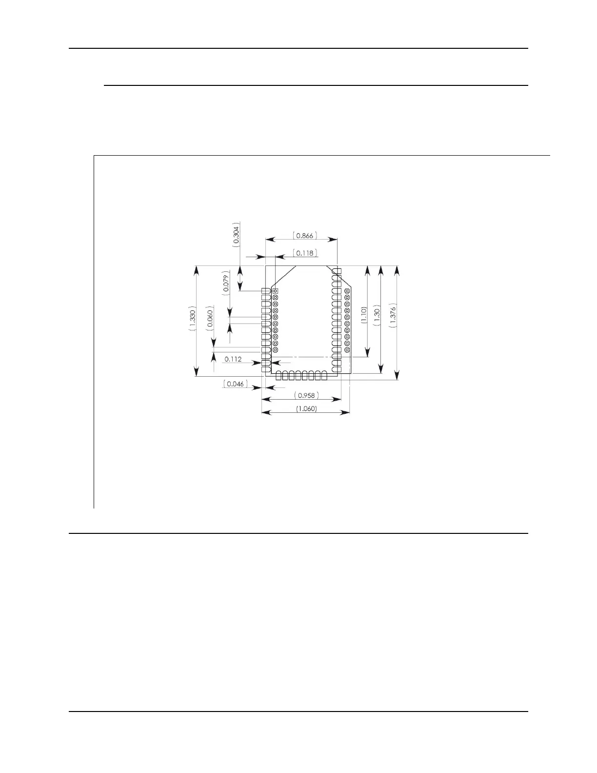
Common Footprint for Through-hole and Surface Mount
Digi has designed a common footprint which will allow either module to be attached to
a PCB. The layout is shown below. The round holes in the diagram are for the Through-
hole version, and the semi-oval pads are for the Surface Mount version. Please note that
pin 1 of the Through-hole version connects with pin 2 of the Surface Mount. By using
the shown diagonal traces to connect the pins, the layout will work for both modules.
Flux and Cleaning
It is recommended that a “no clean” solder paste be used in assembling these modules.
This will eliminate the clean step and ensure unwanted residual flux is not left under the
module where it is difficult to remove. In addition:
• Cleaning with liquids can result in liquid remaining under the shield or in the gap
between the module and the OEM PCB. This can lead to unintended
connections between pads on the module.
• The residual moisture and flux residue under the module are not easily seen
during an inspection process.
Factory recommended best practice is to use a “no clean” solder paste to avoid the
issues above and ensure proper module operation.

 Loading...


