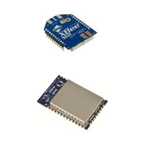
XBee® Wi-Fi RF Modules
© 2013 Digi International, Inc. 28
SPI mode is chip to chip communication. Digi does not supply SPI communication option
on the Device Development Evaluation Boards.
SPI mode can be forced by holding DIO13/DOUT low while resetting the module until
SPI_nATTN asserts. By this means, the XBee Wi-Fi module will disable the UART and go
straight into SPI communication mode. Once configuration is completed, a modem
status frame is queued by the module to the SPI port which will cause the SPI_nATTN
line to assert. The host can use this to determine that the SPI port has been configured
properly. This method internally forces the configuration to provide full SPI support for
the following parameters:
• D1 (note this parameter will only be changed if it is at a default of zero when
method is invoked)
• D2
• D3
• D4
• P2
As long as a WR command is not issued, these configuration values will revert back to
previous values after a power on reset. If a WR command is issued while in SPI mode,
these same parameters will be written to flash. After a reset, parameters that were
forced and then written to flash become the mode of operation. If the UART is disabled
and the SPI is enabled in the written configuration, then the module will come up in SPI
mode without forcing it by holding DOUT low. If both the UART and the SPI are enabled
at the time of reset, then output will go to the UART until the host sends the first input.
If that first input comes on the SPI port, then all subsequent output will go to the SPI
port and the UART will be disabled. If the first input comes on the UART, then all
subsequent output will go to the UART and the SPI will be disabled. Please note that
once a serial port (UART or SPI) has been selected, all subsequent output will go to that
port, even if a new configuration is applied. The only way to switch the selected serial
port is to reset the module.
When the slave select (SPI_nSSEL) signal is asserted by the master, SPI transmit data is
driven to the output pin SPI_MISO, and SPI data is received from the input pin
SPI_MOSI. The SPI_nSSEL pin has to be asserted to enable the transmit serializer to drive
data to the output signal SPI_MISO. A falling edge on SPI_nSSEL causes the SPI_MISO
line to be tri-stated such that another slave device can drive it, if so desired.
If the output buffer is empty, the SPI serializer transmits the last valid bit repeatedly,
which may be either high or low. Otherwise, the module formats all output in API mode
1 format, as described in chapter 7. The attached host is expected to ignore all data
that is not part of a formatted API frame.

 Loading...