DG-GS4900SE Series Installation Guide
10
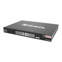
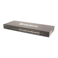
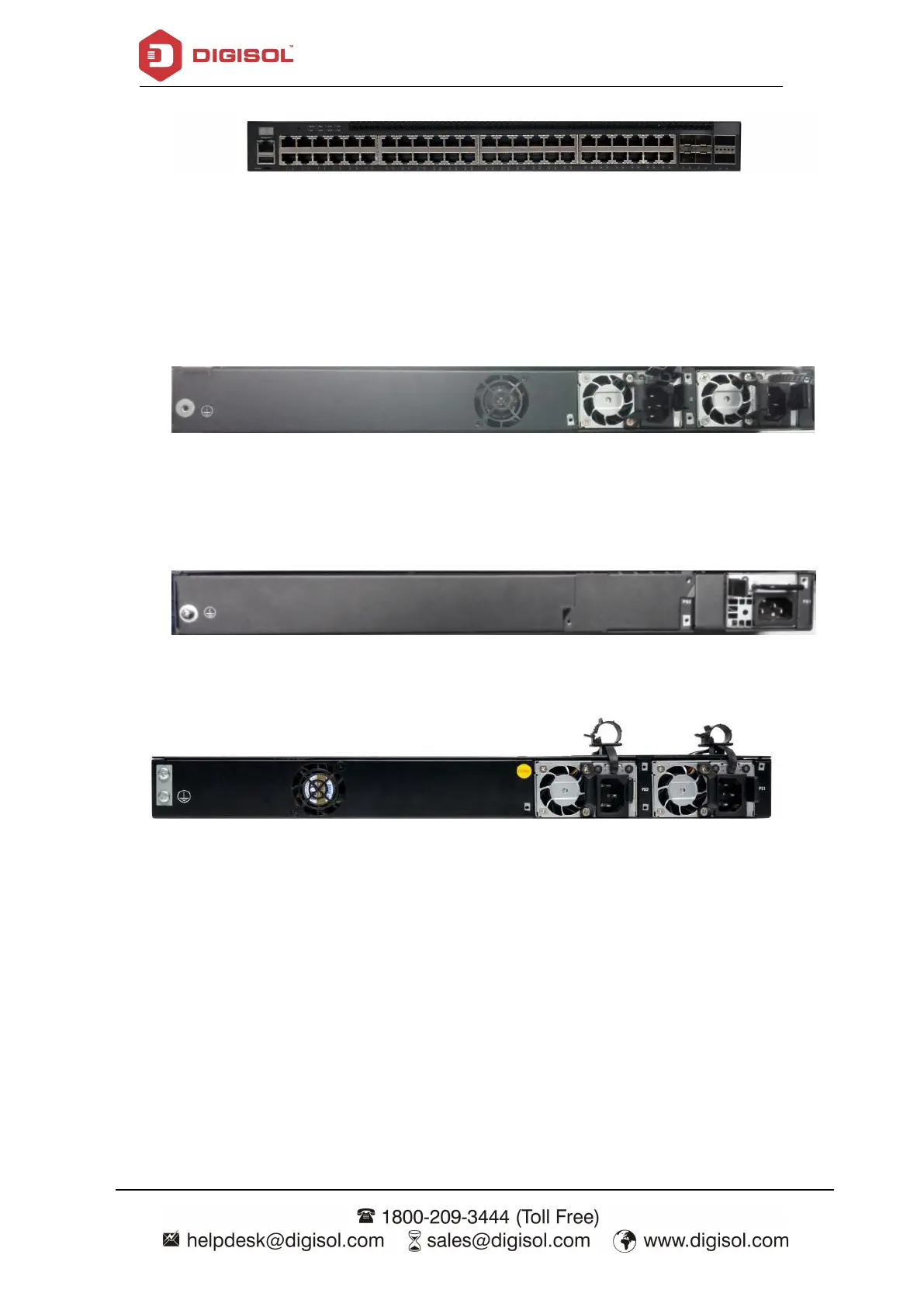
Fig 1- 3 Front Panel of DG-GS4952HPSE
DG-GS4928SE supplies 1 ground screw hole and two power plug-in interfaces.
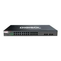
Fig 1- 3Back Panel of DG-GS4928SE
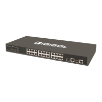
DG-GS4928HPSE2 supplies 1 ground screw hole, 1 fan and two power plug-in
interfaces.
Fig 1- 4Back Panel of DG-GS4928HPSE2
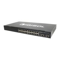
Fig 1- 5 Back Panel of DG-GS4952SE/52HPSE
LEDs of DG-GS4900SE show the corresponding state. Main board LEDs include two
parts, one is 24 1000M interface LEDs (including 4 combo ports), 4 SFP (combo optical
port) interface LEDs and 4 SFP+ interface LEDs. They show each port state at RJ45
plug-in, each port corresponds a LED with double colors.
 Loading...