DG-GS4900SE Series Installation Guide
11
Table 1- 2Port LEDs
On means ports are in the link state
of 10G, 1000M, 100M, 10M
Off means ports are not in the link
state of 10G, 1000M, 100M, 10M
The other is system LEDs, they are used to show the work status of the system at the
right of front panel.
Table 1- 3 DG-GS4900SE System LEDs
Power1 is operating normally
System is operating normally
Power2 is operating normally
The mode is changed to be default
mode
The system mode is the default mode
FAN
(DG-GS492
8HPSE2/52
HPSE
supports)
The fan is working normally
The fan is working abnormally
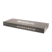
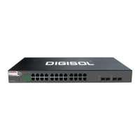
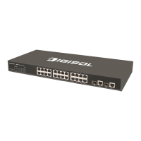
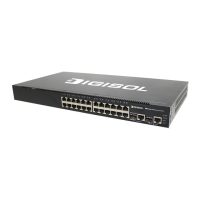
1.4.4 Interface Description of Front Panel
DG-GS4900SE series switches provide RJ-45 1000Mb copper port, interface of
SFP+ 10Gb fiber transceivers and combo interface.
 Loading...