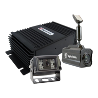
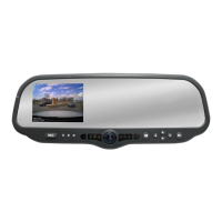
Digital Ally, Inc. | Parts List and System Diagrams
2-6
DVM-800 Installation Guide | 860-00185-00 Rev L
Go Back To Table of Contents
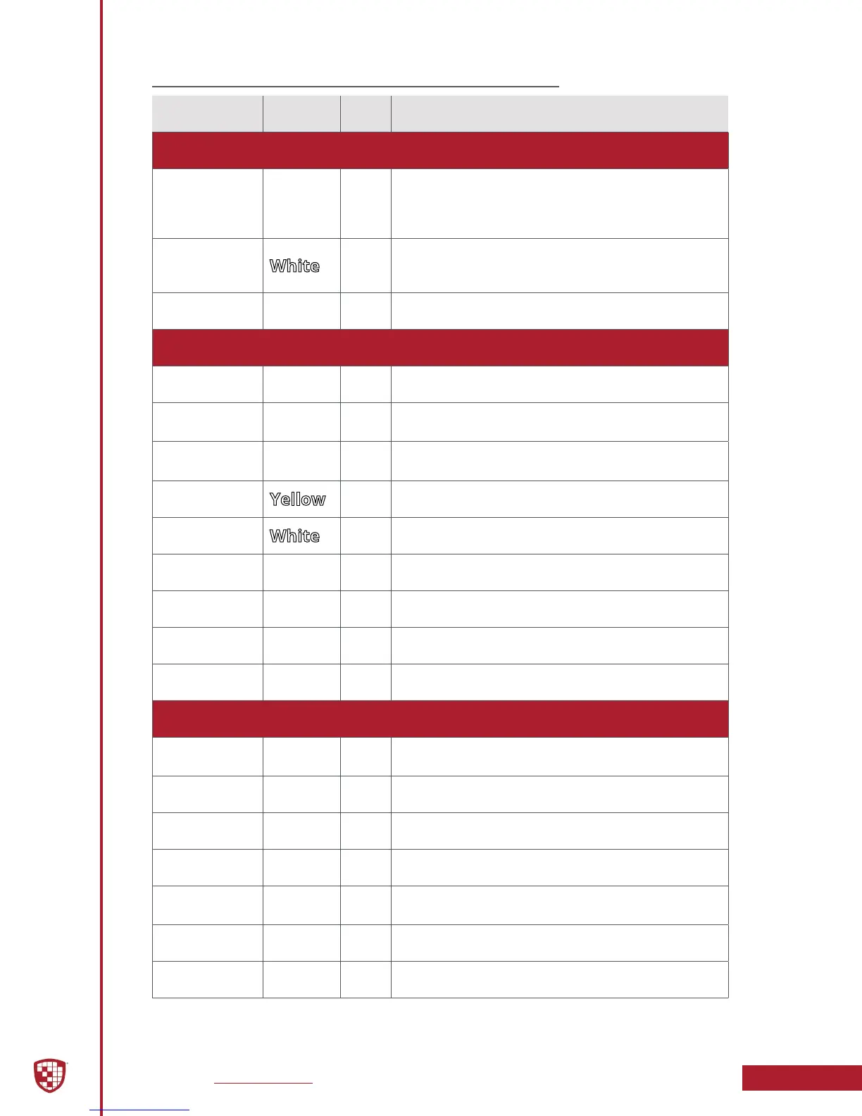
Wiring Connections Chart
Input Signal Color Pin # Description
Main Power Cable (page 3-4)
Battery
Red
1
+13.8VDC Unswitched Power. Connect directly to the
engine compartment battery. DO NOT connect any
Digital Ally equipment through a vehicle charge guard
or battery saver.
Ignition
2
+13.8VDC Switched. Powered only when ignition is in
the ACC or On position. Ignition is used to cycle the
system power on and o.
Ground
Black
3 Chassis Ground. Secure directly to vehicle frame.
Sensor Input Cable (page 3-5)
Reverse
Red
1 Connect to reverse gear relay, or reverse light bulb.
Emergency
Lights
Orange
2
Connect to light bar controller.
+12VDC when emergency lights are activated.
Brakes
Blue
3
Connect to brake pedal switch or 3rd brake light.
+12VDC when brake is active.
VSS
Yellow
4 Connect to Vehicle Speed Sensor pulse signal.
Sensor 5
5 Congurable input sensor
Mic Trigger Out
Green
6 Connect to Green wire of Wireless Microphone Cable
Mic Trigger In
Brown
7 Connect to Brown wire of Wireless Microphone Cable
Ground
Black
8 Chassis Ground
RJ45
RJ45
N/A Connect to “SENS A” RJ45 input of Interface box
DWM Wireless Microphone Cable (page 3-6)
Battery
Red
1
+13.8VDC Unswitched Power. Connect directly to the
engine compartment battery.
Ground
Black
2 Connect to Chassis Ground
Mic Trigger Out
Green
3 Connect to Green wire of Input Sensor Cable.
Mic Trigger In
Brown
4 Connect to Brown wire of Input Sensor Cable.
Remote
Accessory Out
Violet
5 Connect to auxiliary equipment (optional connection)
RJ45
RJ45
N/A Connect to Wireless Microphone Cradle.
Audio
3.5mm
N/A Connect to 3.5mm Ext Mic jack on back of DVM.
 Loading...