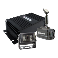
Digital Ally, Inc. | Parts List and System Diagrams
2-4
DVM-800 Installation Guide | 860-00185-00 Rev L
Go Back To Table of Contents
1
2 3
10
4
11
12
13
14 15
16
4
17
18
5
6 7
8
9
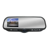
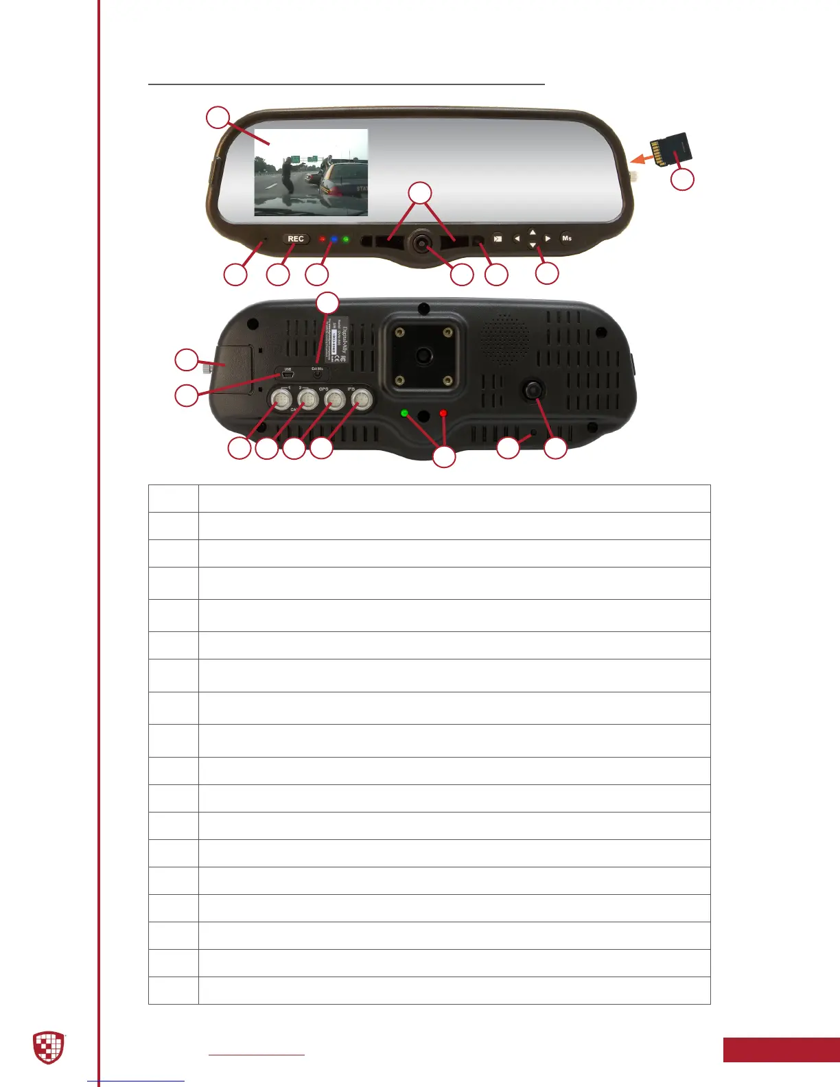
1 LCD Display: Used for viewing video. LCD is behind the mirror and is not visible when o.
2 Internal Microphone: Records audio from the passenger compartment.
3 Manual Record button: This button is used to Start/Stop a manual event recording.
4
LED Status Indicators (Passenger Facing & Road Facing): These visible indicators give the
operator feedback on the operational status of the DVM from inside or outside of the vehicle.
5
Infrared Illuminators: Automatically provides Infrared illumination for the Passenger Facing
Camera during low light conditions.
6 Passenger Facing Camera: Records video of the vehicle passenger area.
7
Ambient Light Sensor: Senses ambient light to automatically adjust LCD brightness and interior
Infrared Illuminators.
8
Menu and Playback Buttons: Used to navigate the DVM menus, play back videos, and log into
the system.
9
SD Card: A removable SD card is installed behind the external SD door. The SD card is installed at
a slight angle and positioned with the connector pads as shown above.
10 External Microphone Input: The Digital Wireless Microphone audio cable is connected here.
11 SD Card door: Provides access to the removable SD memory card.
12 USB Port: For data transfer and Wi-Fi download.
13 Camera 1 Port: An external camera can be connected to the DVM with this port.
14 Camera 2 Port: A 2nd external camera is connected to the DVM here.
15 GPS Port: The GPS antenna is connected here.
16 Power Port: Provides power to the DVM. Also used to connect the Interface Box to the DVM.
17 Reset Button: Used to perform a hard reset of the system.
18 Road Facing Camera: Records the view in front of the vehicle.
DVM Features Diagram
 Loading...