Digital Ally, Inc. | Installation Instructions
3-6
DVM-800 Installation Guide | 860-00185-00 Rev L
Go Back To Table of Contents
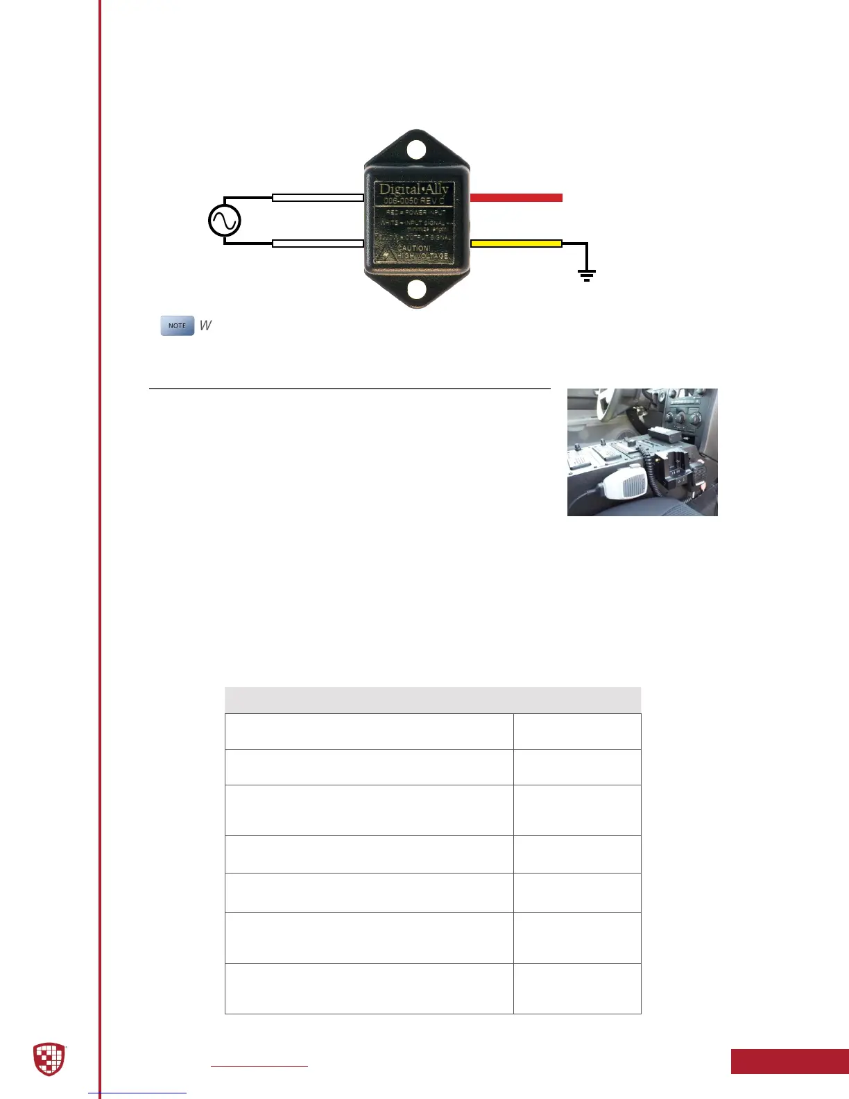
Siren Adapter Interface (optional)
If an acceptable DC output cannot be obtained from the siren controller, the
optional Siren Adapter Interface can be used to connect the siren speaker
to the interface box. Follow the diagram below to install the siren interface.
White
White
Red
Yellow
Siren
Speaker
Output
To DVM-800 HD
IF Box Sensor Input
When using the siren adapter, the input sensor must be congured for a High
to Low, Standard Threshold within the VuVault device conguration.
Step 5: Wireless Microphone Installation
1. Attach the mounting bracket to the back of the
Wireless Microphone Cradle; the assembly can then be
mounted at your preferred location, such as the side
of the center console. Do not mount the cradle in close
proximity to a cup holder or other area which may be
exposed to moisture. Damage caused by a liquid spill
is not covered under warranty.
2. Attach the antenna. If you are using the external In-Car
Microphone, connect it to the DWM Cradle Microphone jack and route
the microphone to your preferred location in the vehicle. The typical
mounting location for the external in-car microphone is in the rear seat
area along the headliner & below the weather strip.
DWM Wireless Microphone Cable Installation
Carefully route the cable to the Ext Mic jack on the back of the DVM. Make the following
connections:
Figure 3-6: Wireless Microphone Cable Connections
Connection Wire Color
Power
Connect to +13.8DVC Battery Terminal
Red
Ground
Connect to vehicle chassis
Black
Remote Accessory Out
Connect to auxiliary equipment
(optional connect, see next page)
Violet
Microphone Trigger Out
Connect to Green wire of IF Sensor Cable
Green
Microphone Trigger In
Connect to Brown wire of IF Sensor Cable
Brown
Transmit/Receive
Connect to RJ45 input jack on the DWM
Microphone Cradle
RJ45
Audio Out
Connect to 3.5mm Ext Mic jack on
the back of the DVM
3.5mm Audio
Plug
 Loading...