Digital Ally, Inc. | Installation Instructions
3-5
DVM-800 Installation Guide | 860-00185-00 Rev L
Go Back To Table of Contents
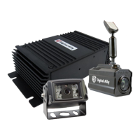
IF Input Sensor Cable Installation
The IF Box provides multi-purpose sensor inputs that allow
external devices to trigger an event record in the mirror.
Common external sensors include; emergency lights, siren,
brake pedal, vehicle speed sensor, reverse gear, covert
foot-switch, or door sensors.
Determine the Device Trigger Signal Level
For the administrator to congure each of the six multi-purpose input sensors, the
signaling from the external device must be found and documented. Determine the
signaling of each external device that will be used and document the signal information
on the Interface Box Sensor Worksheet that has been provided on page 5-3.
1. Position the RJ45 end of the sensor cable near the IF Box RJ45 jack, but
do not plug it into the IF Box yet.
2. Leaving a service loop for connection to the IF Box, begin routing the
non-terminated end of the sensor cable to the desired location in the
vehicle for connection to each of the input sensor devices.
3. Cut o excess cable as required.
4. Use Figure 3-5 below for wiring connections to the sensor cable and
connect the external devices to the appropriate wire of the RJ45 sensor
cable.
5. The Green and Brown wires are reserved for the DWM wireless
microphone system. Connect the wires as shown in below to ensure
microphone activation functions correctly. Use butt splice connectors
to connect the green and brown wires.
6. When all external devices have been connected, plug the RJ45 into the
jack labeled “SENS A” on the IF Box.
Figure 3-5: Input Sensor Connections
Pin Sensor Wire Color
1
Reverse
Reverse Gear Sensor
Red
2
Lights
Connect to +12VDC Light Bar Output
Orange
3
Brakes
Connect to +12VDC Brake Switch
Blue
4
Speed
Connect to VSS Output
(Vehicle Speed Sensor)
Yellow
5
Sensor #5
Congurable Input
6
Mic Trigger Out
Connect to Green wire of DWM harness
Green
7
Mic Trigger In
Connect to Brown wire of DWM harness
Brown
8
Ground
Connect to vehicle chassis
Black
N/A
Sensor In/Out
Connect to “SENS A” input on interface box
RJ45
IF Box Sensor Input Cable
 Loading...