Digital Ally, Inc. | Before You Begin
1-1
DVM-800 Installation Guide | 860-00185-00 Rev L
Go Back To Table of Contents
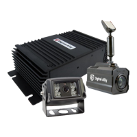
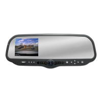
This document references the installation of the DVM-800 system, external cameras,
and the cabling harnesses.
Tools Needed
• #2 Phillips head screwdriver
• #20 Torx screwdriver or bit
• 1/8” (4 mm) at-blade screwdriver
• Digital Volt Meter
• Tie wraps
• 16 Gauge Scotchlok or butt connectors
• Wire Crimpers
Cautions and Notes
Please read the following instructions and precautions before installing the DVM-800.
• For assistance, a qualied installation technician or mechanic should
be consulted.
• Do not use excessive force when removing the mirror from the
windshield. The mirror mounting plate may become separated from
the windshield and/or the windshield may break if excessive force
is used. If you are unfamiliar with rearview mirror removal seek
professional assistance.
• Do not route wiring and cabling over sharp metal edges where they
may become damaged or cut.
• To prevent electrical shorts or breakage in the wiring and cabling, do
not allow wiring and cabling to be pinched behind trim pieces, panels,
or other objects.
• Do not run wires or cables in areas where they may become damaged
by heat from the engine or the exhaust system.
• Do not install any DVM components or wiring in the deployment path
of the air bags.
• When installing the cables or making wire connections, it is
recommended you leave a little slack in the cable connections to allow
for service loops and for adjustment of the mirror so the connections
do not get pulled or accidentally disconnected.
• Do not connect any Digital Ally wiring in series with a vehicle charge
guard or battery saver. All system battery connections must be made
to a constant +13.8VDC location within the vehicle.
• Where possible, do not leave excessive cable above the headliner. We
recommend at least 2 feet of distance between our cabling and that of
other systems which may carry a signal for transmit and/or receive.
Section 1
Before You Begin
 Loading...