Basic Operation
QC1936 Digital Storage Oscilloscope 24
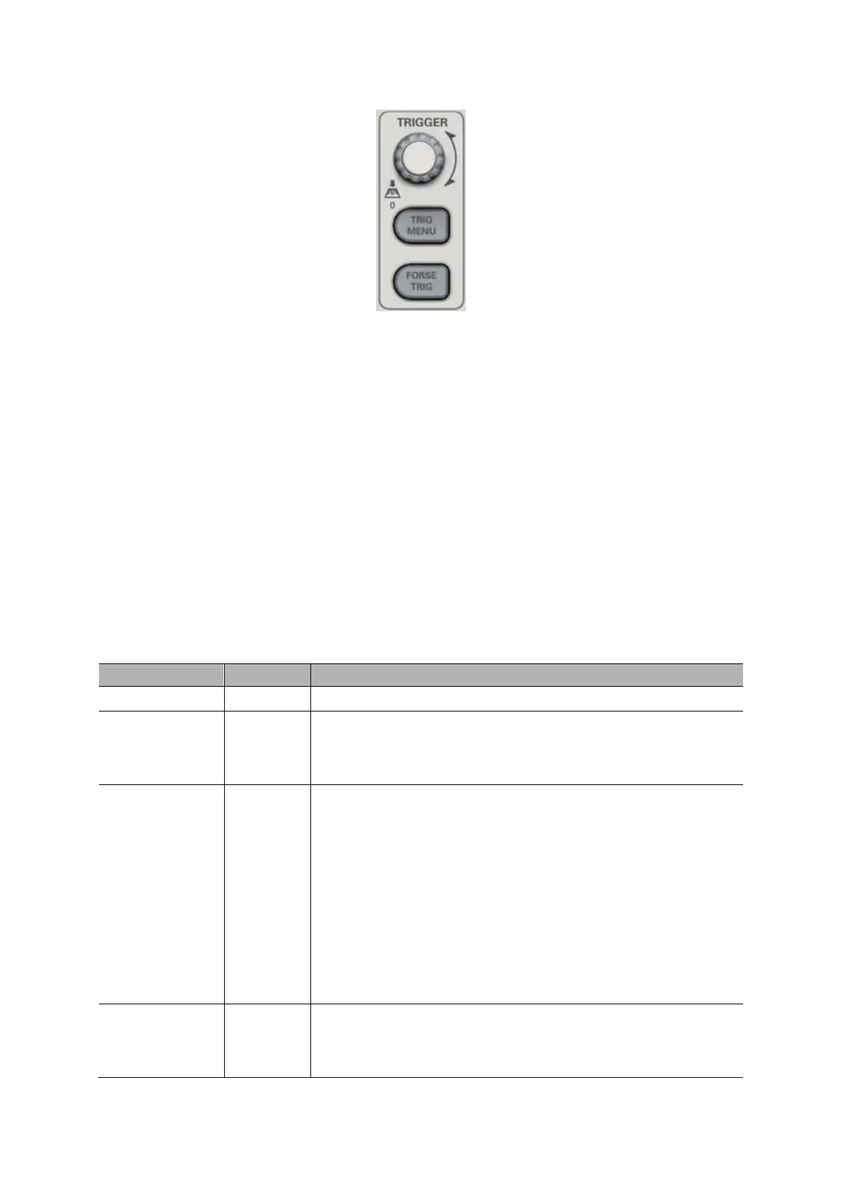
1. Level
It sets the amplitude level the signal must cross to cause an acquisition when using the Edge or
Pulse Width trigger.
2. Set to 50%
The trigger level is set to the vertical midpoint between the peaks of the trigger signal.
3. Force Trigger
Used to complete an acquisition regardless of an adequate trigger signal. This button becomes
useless if the acquisition is already stopped.
4. TRIG MENU
Push this button to display trigger menus. The edge trigger is in common use. See the table below
for details.
Edge Video
Pulse Slope
Swap Overtime
By default the oscilloscope uses the edge trigger which triggers
the oscilloscope on the rising or falling edge of the
input signal when it crosses the trigger level (threshold).
CH1
CH2
EXT
EXT/5
AC Line
Select the input source as the trigger signal.
CH1, CH2: No matter the waveform is displayed or not, a
certain channel will be triggered.
EXT: Does not display the trigger signal and allows a trigger
level range of +1.6V to -1.6V.
EXT/5: Same as EXT option, but attenuates the signal by a
factor of 5 and allows a trigger level range of +8V to -8V.
AC Line: Uses a signal derived from the power cord as the
trigger source.
Select a trigger mode.
By default, the oscilloscope uses the Auto mode. In this mode,
the oscilloscope is forced to trigger when it does not detect a