SETTING BASIC DATA
13
watch this red LED as well, which shows you how sharply the sensor aligns
the bolt head, both at start and end points.
Measurement of distance traveled between 0-100. speed signals:
• In case of individual installation find a possibly non-driven wheel for
speed sensor, where slip rarely occurs.
• In order to reach maximum accuracy in calibration take soil conditions,
tyre pressure, hopper weight (ideally half filled),...etc. into consideration
to create similar conditions to real circumstances.
• Adjust distance between DSI-18 speed sensor (M18 thred) and bolt head
to 4-5 millimeters and consider accidental lateral wheel movement, as
well.
• Proper speed sensor adjustment has vital importance, it should signal at
the proximity of each bolt head. LED indicates it by blinking both on the
sensor and the monitor!
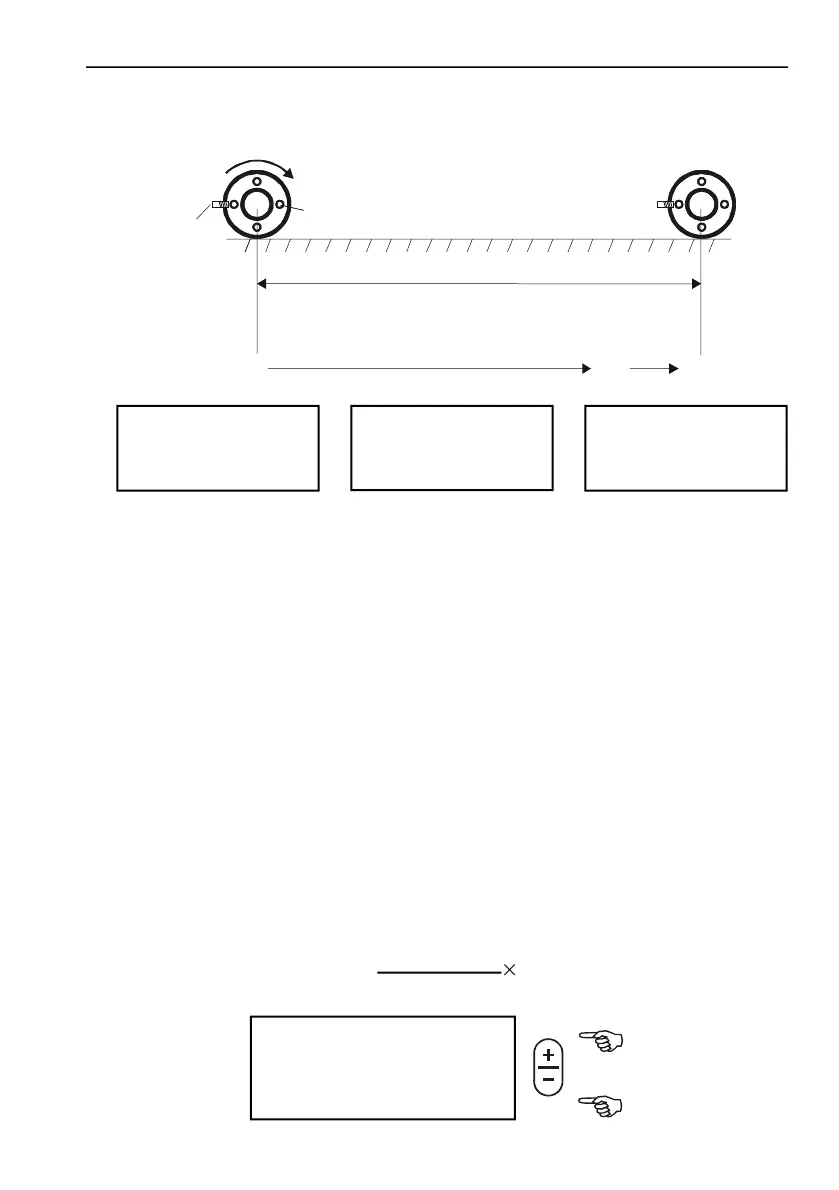
SETTING OF DISTANCE TRAVELED IN 100 SPEED SENSOR
SIGNAL
The distance traveled can be determined either:
• by MEASUREMENT: with a measure tape ( it is always more
accurate method since average slip is also included)
• by CALCULATION: × wheel perimeter (cm)
TU
100|Ü------------|0
START>
TU
100|Ü------------|0
START>
TU
100|Ü------------|0
100
START>
TU ? >
|Ü------------Û|
60.0 m
>
Nomber of speed
signals =
Distance travelled = ??? cm