SETTING BASIC DATA
12
However, skipped rows are not involved in seeding control and are indicated
by a (.) character.
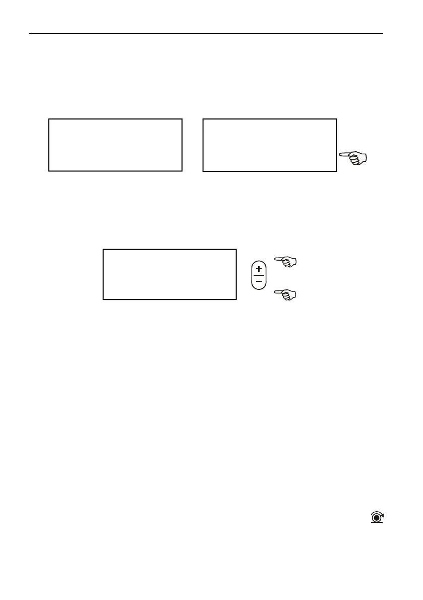
SEEDING ROW DISPLAY SETTING
Enhanced visibility can be reached by doubling the distances of the displayed
seed sensors on screen (up to 8 rows).
If seeder has more than 8 rows, a short warning alarms you at expansion
attempt. This case the program automatically reset short row display.
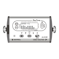
ENTRY OF WORKING WIDTH
Seeding machine working width is adjustable between 0.75-30 meters
This constant is needed for area count.
Working width can be calculated: row number multiplied by row spacing.
100 SPEED SIGNAL COUNT
This is a side function to get information about distance traveled in 100 speed
signals.
Pull/tow seeding machine on field until 100 speed signals are counted, then
measure distance traveled between 0. and 100. signals with a measure
tape on the ground. Enter distance value in the monitor in centimeters. A
warning beep sounds from 90. speed sensor signal to slow down.
Speed sensor is an inductive sensor which detects bolt heads of a driven
wheel.
In case of individual installation the number of signaling bolt heads must be
enough to provide at least one signal at every 30-60 cms distance traveled
and it may not exceed 100 cms.
Readiness for operation is indicated by a flashing SPEED SENSOR LED
on the monitor. Accurate measurement can be reached if speed sensor exactly
aligns bolt head when starting calibration. Besides signal counter on screen
J X >
TU<J |? 4.50 m
J Y
>
B B B B B B B Bf
1 2 3 4 5 6 7 8 >