EN
page 34
7.2.5 Connecting to a steam generator (special versions on request)
Place a steam shut-off valve, nearby.
If the steam pressure exceeds 0.7 Bar, add a pressure reducer.
On the machine outlet, install a condense relief valve with a fl ow rate of at least 25 kg/h.
7.3 Installation
7.3.1 Positioning the machine
Remove the packing with care.
Lift the machine as described in chap. 7.1.1 Handling the product.
Position the machine as shown on the installation diagram (lay-out)
approved at the time of the offer.
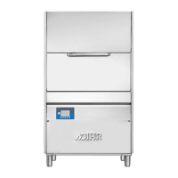
Maintain a minimum distance of about 50 mm from the walls, so that motors
are ventilated (see pict. 5). Install suction hoods to assure proper ventilation
of the room, in order to eliminate steam and excessive humidity.
Check that the machine is properly levelled, by adjusting the legs (see
pict. 6).
Make sure the machine is not standing on the power cable or on the fi lling/
drain hoses. Level the machine fl at, by adjusting the support feet.
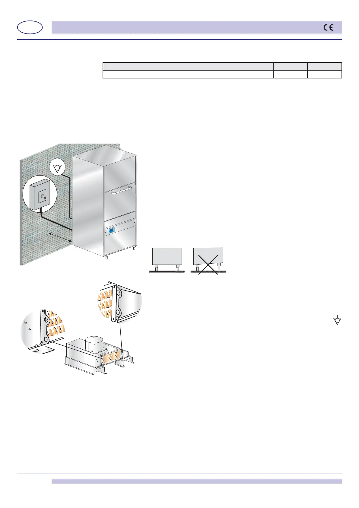
In case of relocation of the machine, DO NOT use the lifting hooks of the
heat exchanger (if installed) to lift the whole machine (see pict. 7).
Those hooks are designed to bear the weight of the heat exchanger only,
not the whole machine.
7.3.2 Electrical connection
The electrical connection shall be carried out in accordance to the local
laws in force.
The machine has a connection at the back, indicated by the symbol
that is meant to link the metal structure and masses among different
apparatuses, to prevent electro-static electrical shocks.
The electrical supply cable must be new, fl exible, and according to "har"
H07RN-F or a local valid equivalent. The cable size is dimensioned
according to the power.
Should the electrical supply cable get damaged it shall be changed by the
Manufacturer, or his Authorized Service, or other technician with equivalent
qualifi cation, to prevent any risk.
If the machine is fi tted with a three-phase pump, check the correct motor rotation (right
rotation as per arrow on the casing).
7.3.3 Water connection
Connect the draining pipe, supplied with the appliance, to the connection elbow located in
the tank bottom.
The drain tube shall always be connected to a siphon in order to prevent the release of odors.
If the water cannot be discharged to a level below the machine drain, it is advisable to install
a drain pump (supplied on request).
Table 2
Pressure table/Water supply Min Max
Static Pressure 0,5 bar 0,7 bar
50 mm
pict. 5
pict. 7
pict. 6