3
AP Dynamometer Service Manual
AP Dynamometer Introduction .............................................................................................................................. 5
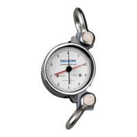
The Dillon Mechanical Dynamometer Family .................................................................................................. 5
About This Manual .......................................................................................................................................... 5
Disassembly and Reassembly .............................................................................................................................. 6
Separation of Pressure Bar and Gauge Movement on 5" Diameter Units up to 20,000 lb/10000 kg ............... 6
Reassembly of Pressure Bar and Gauge Movement on 5" Diameter Units up to 20,000 lb/10000 kg ............ 6
Separation of Pressure Bar and Gauge Movement on 10" Diameter Units up to 20,000 lb/10000 kg ............. 8
Reassembly of Pressure Bar and Gauge Movement on 10" Diameter Units up to 20,000 lb/10000 kg........... 8
Separation of Pressure Bar and Gauge Movement on 10" Diameter Units
from 30,000 -100,000 lb (15000-50000 kg) Capacities ................................................................................... 9
Reassembly of Pressure Bar and Gauge Movement on 10" Diameter Units
from 30,000 -100,000 lb (15000-50000 kg) Capacities ................................................................................... 9
Periodic Maintenance Requirements .................................................................................................................... 11
Cleaning And Lubrication ............................................................................................................................... 11
Inspection of the Pressure Bar ....................................................................................................................... 11
Inspection of the Shackles and Pins ..............................................................................................................12
Defect Removal Allowances for Shackles and Shackle Pins .........................................................................12
Defect Removal Allowances for Pressure Bars ..............................................................................................13
Proof Loading ................................................................................................................................................13
Calibration Procedures .........................................................................................................................................14
Procedure for 20,000 lb (10000 kg) and Below ..............................................................................................14
Span adjustment procedure ....................................................................................................................14
Procedure for 30,000 lb (15000 kg) and Higher .............................................................................................16
Span adjustment procedure ....................................................................................................................16
Pointer Part Numbers...........................................................................................................................................17
Standard 5” (127 mm) Dynamometer ............................................................................................................17
Standard 10” (254 mm) Dynamometer ..........................................................................................................17
Troubleshooting and Common Repairs ................................................................................................................18
Calculating Tension in a System...........................................................................................................................18
5” Dial (500-20,000 lb Cap.) Parts and Assembly .................................................................................................19
10” Dial (500-20,000 lb Cap.) Parts and Assembly ...............................................................................................20
10” Dial (30,000-50,000 lb Cap.) Parts and Assembly ..........................................................................................21
10” Dial (100,000 lb Cap.) Parts and Assembly ....................................................................................................22
Shackle/Pin Dimensional Outline Drawings..........................................................................................................23