8 www.dimplex.com
Installation
2. Turn OFF the main water
supply and drain the line of any
standing water (if possible),
before proceeding to tie into
the water line.
!
NOTE: Once the new plumbing
connections are complete ensure
that the lines are ushed to prevent
any debris from going into the unit.
3. On the cassette, remove the
top cover assemblies (Figure
10, page 18) and prime each of
the water reservoirs with 33.5
oz (1L) of water.
4. Replace the top cover
assemblies and ensure that the
two plumbing caps are securely
attached to the top cover of the
water reservoirs. (Figure 10,
page 18)
5. Locate the ball valve located
in the bottom center of the unit
(near the back). (Figure 1)
6. Attach one end of the ¼ in
(6.4 mm) tubing to the ball
valve. Insert the tubing into the
ball valve tting so that it is fully
inserted (approximately ½ in
(12 mm)).
!
NOTE: Ensure that the end of
the tubing is cut square, to prevent
leaking.
7. Route the tubing to the area of
the water source.
8. Verify that all of the
connections are fully inserted,
and begin opening each of the
valves, ensuring that no leaks
are present.
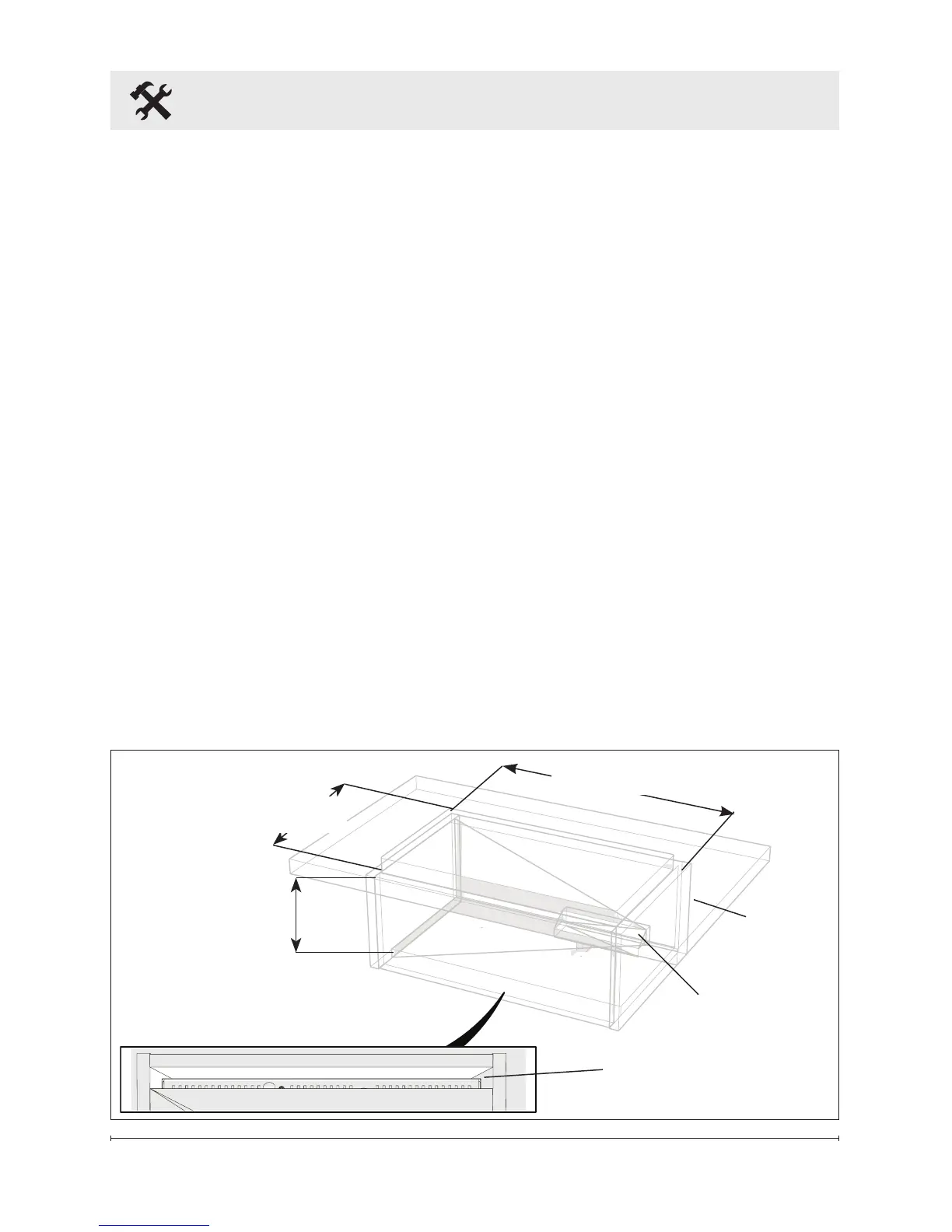
Figure 2
Adjustable from
9 in to 9½ in
(229 mm to 241 mm)
Fresh Air Inlet
CDFI500-PRO: 40 in
2
(258 cm
2
)
CDFI1000-PRO: 80 in
2
(516 cm
2
)
Exit for Electrical
CDFI500-PRO: 20⅜ in (518mm)
CDFI1000-PRO: 40⅜ in (1025mm)
Installation
Surface
Media Plate: 12¼ in (311mm)
Log Set: 14¼ in (362mm)