13
Floating Display Assembly / Main Control
Board Replacement
(Mod B-C units)
Tools Required: Phillips Head Screwdriver
CAUTION: If unit was operating prior to servicing allow
at least 10 minutes for heating elements and top panel to
cool o to avoid accidental burning of skin.
WARNING: Disconnect power before attempting any
maintenance to reduce the risk of electric shock or damage
to persons.
1. Unplug the unit from power outlet.
2. Remove the rebox from the front of the mantel and
remove front glass assembly (glass lifts o).
CAUTION: Even though the glass is safety glass it
may break if bumped, struck of dropped. Care must be
taken when handling the glass.
3. Remove the loose media from the unit (if applicable).
4. Remove the 14 screws around the back panel of the
rebox and one in the middle of the panel (Figure 2).
5. Locate the oating display assembly. (Figure 4)
6. Transfer the connections from the existing board to the
new display/control board.
7. Remove the 4 screws securing the board to the assembly.
8. Properly orient and insert the new oating display as-
sembly.
9. Reassemble in the reverse order as above.
Relay Board Replacement
(Mod B-C units)
Tools Required: Phillips Head Screwdriver
CAUTION: If unit was operating prior to servicing allow
at least 10 minutes for heating elements and top panel to
cool o to avoid accidental burning of skin.
WARNING: Disconnect power before attempting any
maintenance to reduce the risk of electric shock or damage
to persons.
1. Unplug the unit from power outlet.
2. Remove the rebox from the front of the mantel and
remove front glass assembly (glass lifts o).
CAUTION: Even though the glass is safety glass it
may break if bumped, struck of dropped. Care must be
taken when handling the glass.
3. Remove the loose media from the unit (if applicable).
4. Remove the 14 screws around the back panel of the
rebox and one in the middle of the panel (Figure 2).
5. Locate the relay board assembly. (Figure 4)
6. Transfer the connections from the existing board to the
new display/control board.
7. Remove the 4 screws securing the board to the assembly.
8. Properly orient and insert the new oating display as-
sembly.
9. Reassemble in the reverse order as above.
Power Supply Replacement
(Mod B-C units Only)
Tools Required: Phillips Head Screwdriver
CAUTION: If unit was operating prior to servicing allow
at least 10 minutes for heating elements and top panel to
cool o to avoid accidental burning of skin.
WARNING: Disconnect power before attempting any
maintenance to reduce the risk of electric shock or damage
to persons.
1. Unplug the unit from power outlet.
2. Remove the rebox from the front of the mantel and
remove front glass assembly (glass lifts o).
CAUTION: Even though the glass is safety glass it
may break if bumped, struck of dropped. Care must be
taken when handling the glass.
3. Remove the loose media from the unit (if applicable).
4. Remove the 14 screws around the back panel of the
rebox and one in the middle of the panel (Figure 2).
5. Locate the power supply assembly. (Figure 4)
6. Disconnect the power supply from the relay board and
the display/control board and install the new power
supply in their place.
7. Remove the 4 screws securing the assembly to the
unit.
8. Properly orient and insert the new power supply as-
sembly.
9. Reassemble in the reverse order as above.
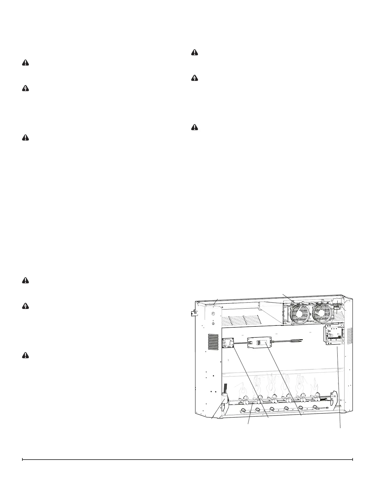
Mod B
gWave
TM
Assembly
Flicker Motor
Relay Board
Main Board/Floating
Display Assembly
Heater Assembly
Top LED Light
Media LED Light Assembly
Power Supply
Figure 4