12 www.dimplex.com
Main Control Board Replacement
(Mod 0-A units)
Tools Required: Phillips Head Screwdriver
Flat Head Screwdriver
Needle Nose Pliers
CAUTION: If unit was operating prior to servicing allow
at least 10 minutes for heating elements and top panel to
cool o to avoid accidental burning of skin.
WARNING: Disconnect power before attempting any
maintenance to reduce the risk of electric shock or damage
to persons.
1. Unplug the unit from power outlet.
2. Remove the rebox from the front of the mantel and
remove front glass assembly (glass lifts o).
CAUTION: Even though the glass is safety glass it
may break if bumped, struck of dropped. Care must be
taken when handling the glass.
3. Remove the loose media from the unit (if applicable).
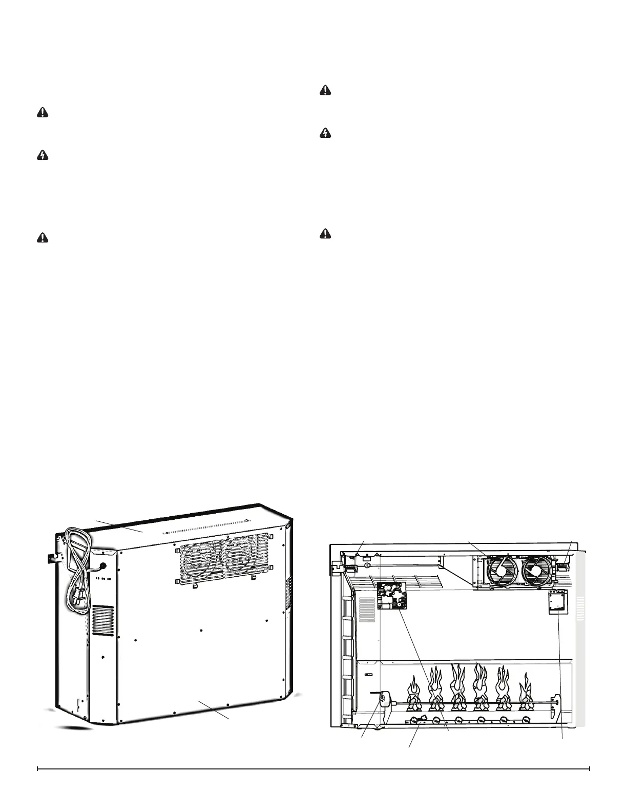
4. Remove the 14 screws around the back panel of the
rebox and the 3 along the middle of the panel (Figure
2).
5. Locate the main control board and transfer the wir-
ing connections from the old board to the new board.
(Figure 3)
!
NOTE: A at head screwdriver can be used to gently
pry between the end of the connector and the main control
board to release the wires.
6. Release the main control board from the unit by using
needle nose pliers to depress the tab on the mounting
standos and gently lift the driver board o.
7. Properly orient and insert the new main control board.
8. Reassemble in the reverse order as above.
Figure 2
Floating Display Assembly
(Mod 0-A units)
Tools Required: Phillips Head Screwdriver
CAUTION: If unit was operating prior to servicing allow
at least 10 minutes for heating elements and top panel to
cool o to avoid accidental burning of skin.
WARNING: Disconnect power before attempting any
maintenance to reduce the risk of electric shock or damage
to persons.
MOD 0-A
1. Unplug the unit from power outlet.
2. Remove the rebox from the front of the mantel and
remove front glass assembly (glass lifts o).
CAUTION: Even though the glass is safety glass it
may break if bumped, struck of dropped. Care must be
taken when handling the glass.
3. Remove the loose media from the unit (if applicable).
4. Remove the 14 screws around the back panel of the
rebox and the 3 along the middle of the panel (Figure
2).
5. Locate the oating display assembly. (Figure 3)
6. Remove the 2 screws located at the top of the assem-
bly, gently remove the board and surrounding bracket.
7. Follow the wiring to the main control board and replace
with new connection.
8. Properly orient and insert the new oating display as-
sembly.
9. Reassemble in the reverse order as above.
Figure 3
gWave
TM
Assembly
Flicker Motor
Main Control Board
Floating Display
Assembly
Heater Assembly
Top LED Light
Flame LED Light Assembly
Back Panel
Top Panel
Mod 0-A