DNDS Modular
DNDS Modular DNDS Modular
DNDS Modular
O
OO
Original
riginal riginal
riginal Betriebsanleitung
BetriebsanleitungBetriebsanleitung
Betriebsanleitung
Original Instruction Manual
Original Instruction Manual Original Instruction Manual
Original Instruction Manual
Paralleler Anschluss der Ausgänge
Parallel connection of the outputs
Serial connection of the outputs
Not-Halt Kreis
44
43
34
33
13
14
23
24
STOP
SPEED1
L1
L2
DNDS
Maschinennetz
DNDS
Quit
Schutztürschalter
11 13
12
14
21 23
22
24
68
67
58
57
SPEED2
Netz/ Net
E1
E2
Q
24V DC
CNC
Emergency stop
circuit
Protection cover
switch
entriegeln
Tür
Cover
unlock
Machine net
Quit
24V DC
44
43
34
33
13
14
23
24
L1
L2
DNDS
11 13
12
14
21 23
22
24
68
67
58
57
E1
E2
Q
24V DC
Not-Halt Kreis
Emergency stop
circuit
Schutztürschalter
Protection cover
switch
Quit
Maschinennetz
Machine net
Netz/ Net
Tür
entriegeln
Cover
unlock
STOP
SPEED1
SPEED2
DNDS
CNC
Quit
24V DC
Fehler und Störungen
LED rechts und links am Ein- und Ausgangsmodul sind dunkel.
Ursachen: Kein Messsystem.
Sensorfehler an Klemme IN1 oder IN2 oder an beiden
LED rechts und links am Ausgangsmodul sind dunkel.
Ursachen: Die Klemme E1 oder E2 oder beide sind offen
Die LED links und rechts am Ausgangsmodul blinken kurz grün.
Ursachen: Ein Kontakt schließt oder öffnet nicht.
Zeiteinstellung nicht in beiden Kanälen gleich.
Faults and Errors
LED right and left at the input and output module are dark.
Reason: No measuring system
Sensor failure at the terminal IN1 or IN2 or both
LED right and left at the output module are dark.
Reason: Terminal E1 or E2 or both are not connected to 24V
The LED left and right at the output module flash short green:
Reason: A contact does not close or open.
ime adjustment is not the same in both channels.
GMG, GM
GMG, GMGMG, GM
GMG, GM
0V
STOP
SPEED
UB
64
63
54
53
24
23
14
13
SPEED2
STOP
A1
33
34
43
44
SPEED1
A2
24V
DC
GM / GMG
A1
24V
DC
0.5A
A2
0V
DINA ELEKTRONIK
D-72649 WOLFSCHLUGEN
ID-No:10GM00
DNDS GM
1ZD7
US LISTED
IND.CONT.EQ
R
L
U
STOP
SPEED1
SPEED2
P.D. B300
DC1: 6A DC13: 4A
AC1: 6A AC15: 3A
B
G
-
P
R
U
F
Z
E
R
T
ET 13012
Sicherheit geprüft
tested safety
44
43
34
33
24
23
14
13
64
63
54
53
A2
A2
A2
A2
A1
A1
A1
A1
DNDS MODULAR OUTPUT MODULE
ON
SPEED
STOP
GM / GMG
V1
0V
STOP
SPEED
UB
68
67
58
57
24
23
14
13
SPEED2
STOP
A1
33
34
43
44
SPEED1
A2
24V
DC
A1
24V
DC
0.5A
A2
0V
DINA ELEKTRONIK
D-72649 WOLFSCHLUGEN
ID-No:10GV00
DNDS GM V1
1ZD7
US LISTED
IND.CONT.EQ
R
L
U
STOP
SPEED1
SPEED2
P.D. B300
DC1: 6A DC13: 4A
AC1: 6A AC15: 3A
B
G
-
P
R
U
F
Z
E
R
T
ET 13012
Sicherheit geprüft
tested safety
44
43
34
33
24
23
14
13
68
67
58
57
A2
A2
A2
A2
A1
A1
A1
A1
DNDS MODULAR OUTPUT MODULE
ON
SPEED
STOP
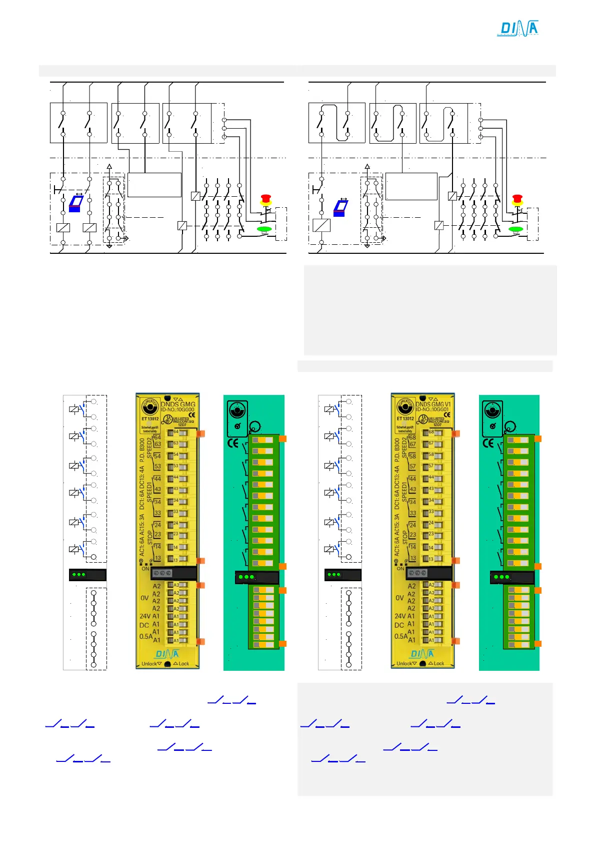
Für Stillstandsüberwachung 2 Kontakte
13 14 23
24
„STOP“
Für Drehzahlüberwachung 2 Ausgänge je mit 2 Kontakten
33 34 43
44
SPEED 1 und
53 54 63
64
SPEED 2 unverzögert
Die Rack Einstellung der erfolgt werkseitig. Siehe Seite 7.
Verwendung des Ausgangs
13 14 23
24
•
13 14 23
24
öffnen bei Bewegung, die LED links ist dunkel
• Diese schließen im Stillstand, die LED links leuchtet.
• Die Kontakter können zur Verriegelung einer
Schutzeinrichtung im Automatikbetrieb eingesetzt werden.
For standstill monitoring 2 contacts
13 14 23
24
„STOP“
For speed monitoring 2 outputs each with 2 contacts
33 34 43
44
„SPEED1“ and
53 54 63
64
SPEED 2 undelayed
The rack configuration happens factory-made. See page 7.
Usage of the output
13 14 23
24
•
13 14 23
24
open in motion and LED left is dark
• This close at standstill, LED left is green.
• The contacts can be used to lock the safety cover during
the automatic function mode.
 Loading...
