DNDS Modular
DNDS Modular DNDS Modular
DNDS Modular
O
OO
Original
riginal riginal
riginal Betriebsanleitung
BetriebsanleitungBetriebsanleitung
Betriebsanleitung
Original Instruction Manual
Original Instruction Manual Original Instruction Manual
Original Instruction Manual
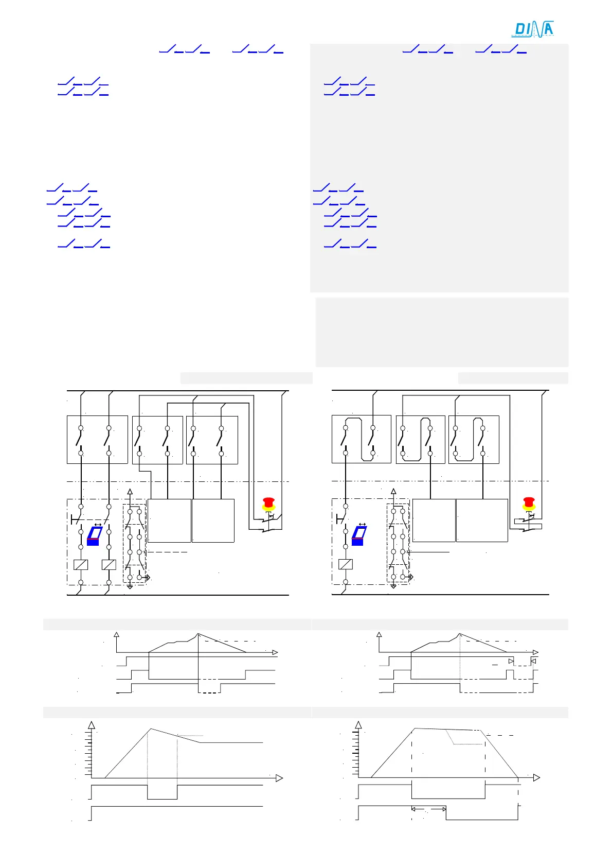
Verwendung der Ausgänge
und
• Diese Ausgänge ermöglichen die Teilung des Antriebsver-
bunds in 2 Kreisen.
•
33 34 43
44
öffnen sofort bei V>Vmax für Not-Halt Kreis 1.
•
53 54 63
64
öffnen sofort bei V>Vmax für Not-Halt Kreis 2.
• LED “SPEED” ist dunkel.
• Über diese Kontakte kann z. B. die Regelfreigabe der
Antriebe unterbunden werden, in dem Kreis in dem V>Vmax.
• Alle Kontakte schließen bei V<90% von Vmax bei nicht
aktiven Wiedereinschaltsperre an den Eingangsmodulen.
• Die LED rechts leuchtet wieder.
DNDS GMG / GM V1
Für Drehzahlüberwachung 2 Ausgänge je mit 2 Kontakten
33 34 43
44
SPEED1, unverzögert und
57 58 67
68
SPEED2, 0.5s rückfallverzögert, 2s bei Version T2
•
33 34 43
44
öffnen sofort bei V>Vmax
•
57 58 67
68
öffnen bei V>Vmax, wenn nach der Rückfallzeit
V>90% von Vmax (Bremsüberwachung).
•
57 58 67
68
bleiben geschlossen, wenn nach der
Rückfallzeit V<90% von Vmax.
• Die LED rechts ist dunkel bei V>Vmax.
• Diese leuchtet bei V<Vmax
Die Einstellung der am Rack erfolgt werkseitig. Siehe Seite 7.
Usage of the outputs
and
• These outputs enable the splitting of the drive circuit in
two circuits.
•
33 34 43
44
open undelayed if V>Vmax for circuit 1.
•
53 54 63
64
open undelayed if V>Vmax for circuit 2.
• The LED “SPEED” is dark.
• The regulation of the drives can be stopped by these
contacts only in the circuit with V>Vmax.
• All contacts close again at V<90% of Vmax if the restart
interlock is not active. See input modules.
• The LED right is on again.
DNDS GMG / GM V1
For motion monitoring 2 outputs each with 2 contacts
33 34 43
44
SPEED1, undelayed and
57 58 67
68
SPEED2, 0.5s off delayed, 2s versionT2
•
33 34 43
44
open undelayed at V>Vmax
•
57 58 67
68
open at V>Vmax if at the end of the delay
time V>90% of Vmax (brake monitoring).
•
57 58 67
68
remain closed if at the end of the delay time
V<90% of Vmax.
• The LED right is dark at V>Vmax.
• The LED is on again at V<Vmax
The rack configuration happens factory-made. See page 7.
LED SPEED und STOP am Ein- und Ausgangsmodul sind dunkel.
Ursachen: Kein Messsystem.
Sensorfehler an Klemme IN1, IN2 oder an beiden
LED links und rechts auf dem Ausgangsmodul blinken kurz grün:
Ursachen: Ein Kontakt schließt oder öffnet nicht.
LED right and left at the in- and output module are dark.
Reason: No measuring system
Sensor failure at the terminal IN1 or IN2 or both
LED left and right on the output module flash short green:
Reason: A contact does not close or open.
NOT-HALT
Kreis 1
44
43
34
33
13
14
23
24
L1
L2
DNDS
11 13
12
14
21 23
22
24
64
63
54
53
24V DC
NOT-HALT
Kreis 2
STOP
SPEED1
SPEED2
DNDS
CNC
Emergency
stop circuit 1
Emergency
stop circuit 2
Schutztürschalter
Protection cover
switch
Quit
Tür
entriegeln
Cover
unlock
NOT-HALT
Kreis 1
44
43
34
33
13
14
23
24
STOP
SPEED1
L1
L2
Tür entriegeln
DNDS
DNDS
Quit
Schutztürschalter
11 13
12
14
21 23
22
24
64
63
54
53
SPEED2
24V DC
CNC
N
OT-HALT
Kreis 2
Emergency
stop circuit 1
Emergency
stop circuit 2
Protection cover switch
Cover unlock
UB
13-14/ 23-24
33-34/ 43-44
V
V>Vmax.
t
53-54/ 63-64
UB
13-14/ 23-24
33-34/ 43-44
V
V>Vmax.
t
>2s
53-54/ 63-64
V
100%
60%
V < 90%Vmax
33-34
43-44
57-58
67-68
40%
20%
t
t
r
V
100%
60%
33-34
43-44
57-58
67-68
40%
20%
90%
t
(0,5s)
V > 90% Vmax
 Loading...
