Do you have a question about the Dini Argeo DGT4X and is the answer not in the manual?
Details on connecting load cells to the transmitter, including sense connections.
Information on power requirements, consumption limits, and UL approved models.
Explains the function of buttons in configuration and weighing modes.
Describes the meaning of various status indicator lights on the device.
Settings for operating modes like DEP.CH or IND.CH.
Adjusting capacity, resolution, and decimal point for the scale.
Covers theoretical and sample weight calibration steps.
Configuration for digital inputs and outputs.
Configuration for RS485 port and load cell exclusion.
Details on digital equalization box mode for load cell data.
Details on multi-scale mode for managing independent scales.
Setting the maximum measurable weight for the scale.
Step-by-step guide for theoretical calibration of load cells.
Procedure for zeroing the mechanical tare (pre-tare).
Guide for calibrating the scale using sample weights.
Verifying the signal of each load cell.
Configuring the functionality of digital inputs.
Configuring the functionality of digital outputs.
How to program output setpoint values.
Setting the address and baud rate for the RS485 port.
Temporarily excluding a broken load cell from the system.
Registers for gross weight and net weight values.
Register detailing input status and scale conditions.
Registers for command results and digital output status.
Registers for mV/V values of individual load cells.
Status registers for each of the 4 scales.
Registers for the gross weight of each of the 4 scales.
Registers for the net weight of each of the 4 scales.
Register for sending commands like zeroing or taring.
Registers for providing parameters for commands.
| Model | DGT4X |
|---|---|
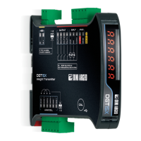
| Type | Weight Transmitter |
| Serial Ports | RS232, RS485 |
| Protocols | Modbus RTU, ASCII |
| A/D Converter | 24-bit |
| Power Supply | 12-24 Vdc |
| Operating Temperature | -10°C to +40°C |
| Load Cell Input | Up to 8 load cells (350 Ohm) |
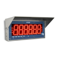
| Display | 6-digit LED |
| Modulation | GFSK |