PTU-D46 User’s Manual (v2.14.0) INSTALLATION & INITIAL SETUP
page 5
3.2 RS-232 Cable and Host Settings
An RS-232 terminal or host computer connects to the female DB-9 connector on the Pan-Tilt
Unit Controller (PTU-C). The host terminal or computer should be set to 9600 baud, 1 start bit, 8
data bits, 1 stop bit, and no parity. Hardware handshaking and XON/XOFF are not used.
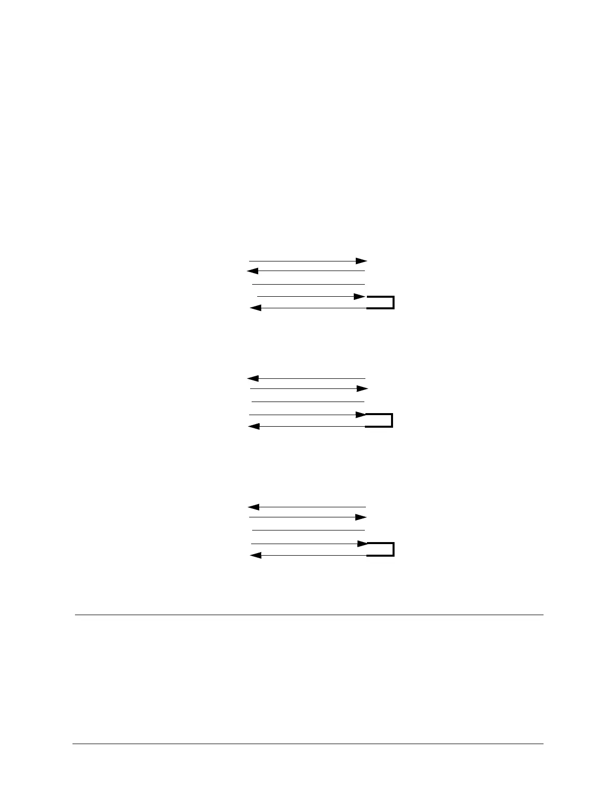
The RS-232 connections to the Pan-Tilt Controller female DB-9 are: TxD (pin 2), RxD (pin
3), and GND (pin 5). You will need to obtain a cable that connects the host RS-232 port to the
controller DB-9 connector. Figure 3 shows cable configurations for some common computer
hosts. Since TxD and RxD assignments to pins 2 and 3 can vary on host computers, try using a
null modem if your initial connection does not work.
Figure 3: RS-232 Pan-Tilt Controller Connection to Common Hosts
PTU-C
(female DB-9)
RxD (pin 3)
TxD (pin 2)
GND (pin 5)
IBM PC, XT
Asynch Card DB-25S
TxD (pin 2)
RxD (pin 3)
GND (pin 7)
PTU-C
(female DB-9)
TxD (pin 2)
GND (pin 5)
IBM AT
Asynch Card DB-9S
RxD (pin 2)
TxD (pin 3)
GND (pin 5)
PTU-C
(female DB-9)
TxD (pin 2)
RxD (pin 3)
GND (pin 5)
Apple Macintosh
8 Pin Mini-DIN
TxD (pin 3)
RxD (pin 5)
GND (pin 4)
RxD (pin 3)
Null modem may
be required.
DTR (pin 4)
DSR (pin 6)
DTR (pin 20)
DSR (pin 6)
(pin 4)
(pin 6)
(pin 4)
(pin 6)
DTR (pin 1)
(pin 4)
(pin 6)
DSR (pin 2)